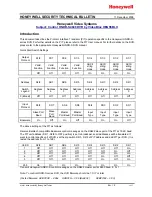
4-8
DNW-A100/A50/A45
DNW-A100P/A50P/A45P
0.5
3.0
5.0
5.75 MHz
4.0
1.5
Before adjustment
After adjustment
Specification: Fluctuation level is minimum.
0.5 to 5.0 MHz : REF
±
11 % (0
±
1.0 dB)
5.75 MHz : REF % (0 dB)
+
0
– 24
+
0
– 3.0
[|Supplement|]
The signal after looping is displaied in a state of overlapping on 1st signal on the screen of the waveform monitor.
They appear that the 1st signal is freezing and the signal after looping is changing the fluctuation level.
4-1. DEC-65 Board (BKDW-505/506)
4. Analog Composite Input Frequency Response Adjustment
(1) Connect as connection 1.
(2) Select A26: DEC VR (LOOP) of A2: AUDIO/VIDEO ADJUST of the maintenance mode.
(3) Select “VIDEO FREQ COMP”.
n
The MULTI burst signal is output from the video test signal generator in this unit.
(4) Adjust “VIDEO FREQ COMP” that the fluctuation level of VIDEO OUTPUT COMPOSITE 2
output signal is minimum.
(5) Regard 1st signal of each frequency as 100%(REF), then check that the level of signal after looping
satisfies the specifications.
(6) After completing the adjustment, push the MENU button once so as to exit A26: DEC VR (LOOP).
(7) Select A2F: NV-RAM CONTROL and save the adjusted data in NV-RAM (execute “SAVE ALL
ADJUST DATA”).
(8) Check that the message “Save Complete” is displayed on the video monitor screen.
(9) Push the MENU button once so as to exit A2F: NV-RAM CONTROL.