7-21
DNW-A100/A50/A45
DNW-A100P/A50P/A45P
Height adjustment nut
TG-0
TG-1
TG-2
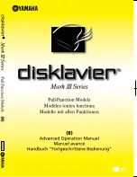
<Fig. 1>
Markers
RF max
80%
Overlap(entrance)
Turn 30
d
more
TG-1
State of step (5)
A
B
C
D
E
F
G
H
S100
RV100(Tracking VR)
J
K
L
M
N
P
R
1
2
<SS-63 board, side A>
7-1-3. Video Tracking Check and Adjustment
.
Alignment tape : SR2-1/SR2-1P (00:00 to 15:00)
(Tracking VR : Effective)
Adjustment
Drum Entrance Side
12. Change the Mode Setting
(1) Press the SET button to cancel the SWITCH-
ING PB mode.
(2) Turn the search dial while pressing the JOG
button so that the “FULL PB” is indicated,
and press the SET button.
n
After that, the overlap portion appears on the
RF waveform.
13. Adjust the Tracking at Drum Entrance
Side
(1) Play back the SR2-1/P (00:00 to 15:00).
(2) Push S100 switch on the SS-63 board more
than 1 sec. so that the tracking VR becomes
to be effective.
(3) Turn RV100 on the SS-63 board clockwise
and adjust the center portion of the RF
envelope waveform makes 80% of the
maximum output level.
(4) Loosen the upper flange of TG-2, and turn
the upper flange so that the tape does not in
contact with the upper flange of TG-2.
(5) Turn the height adjustment nut of TG-1 so
that the overlap portion of the entrance side
of the RF envelope waveform makes flat.
(Fig. 1)
If the waveform does not make flat, perform the
check described below.
1
Clean the drum lead with a bamboo stick.
(Refer to Section 5-2-4 of Maintenance
Manual Part 1.)
2
Press down the tape by bamboo stick very
lightly and check that the tape is running
along the drum lead.
(6) Turn the height adjustment nut of TG-1
clockwise 30
d
more from the state of the step
(5).
n
Turning the height adjustment nut causes the
waveform of the overlap portion to be not
flat.
(7) Turn the upper flange of TG-2 to clockwise
so that the upper flange contacts the tape.
– Continued on the next page. –