background image

4-21

CSM-200

6.

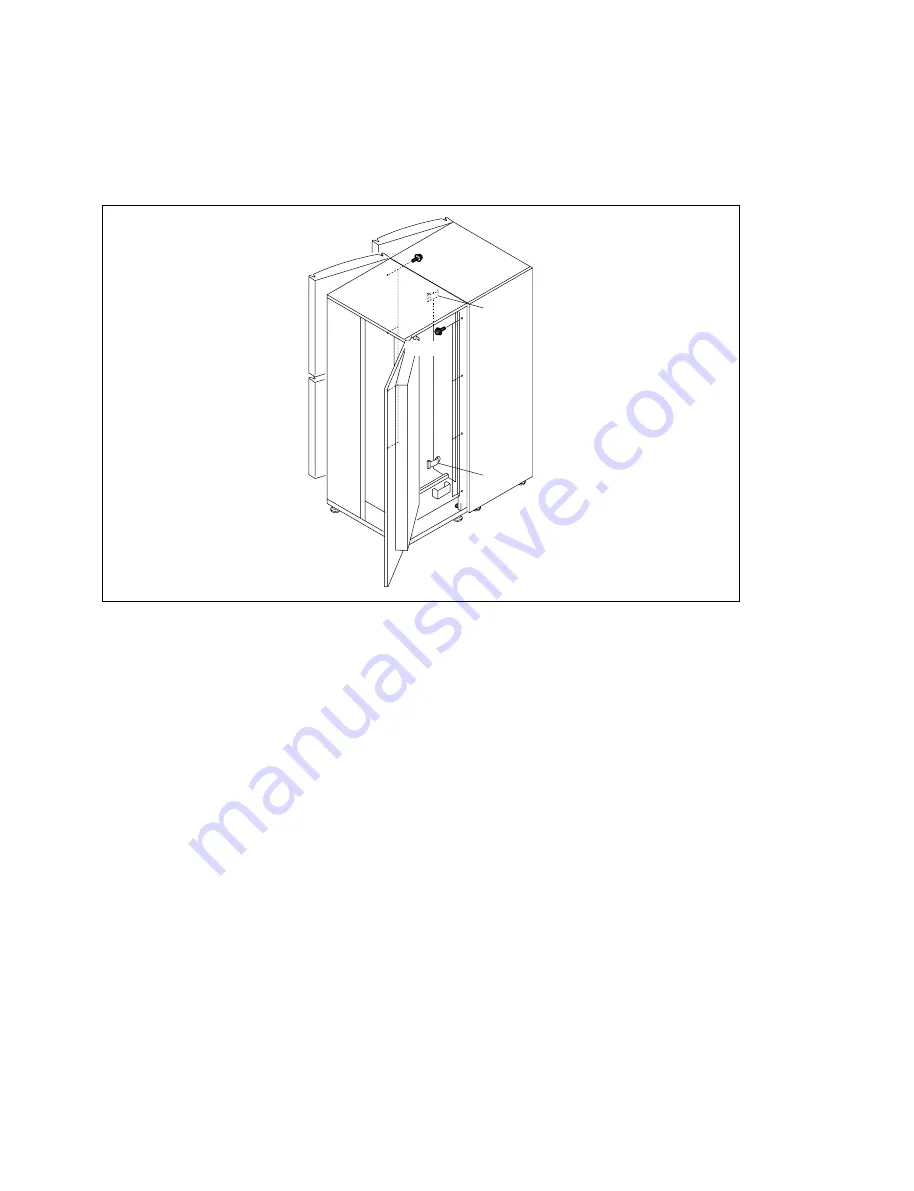
Tighten both of the Basic storage system and the extension console with the eight hexagon head cap
bolts (M4 

x

 8) supplied with the extension console.

7.

Connect the two flat cables (50-pins and 26-pins) coming from the Basic storage system to the
connectors of the extension console.

8.

Attach all of the blank panels (1U) of the extension console that are removed in step 4.

M4 

x

 8

M4 

x

 8

26 pin

50 pin

Summary of Contents for CSM-100BF

Page 1: ...CONSOLIDATED STORAGE MANAGEMENT SYSTEM CSM 200B 200BF 200BS CSM 100B 100BF 100BS CSM 60B 60BF 60BS CSM 200D CSM 200C INSTALLATION MANUAL 1st Edition Revised 10 ...

Page 2: ...den Um die Gefahr eines elektrischen Schlages Feuergefahr und Verletzungen zu vermeiden sind bei Wartungsarbeiten strikt die Angaben in der Anleitung zu befolgen Andere als die angegeben Wartungsarbeiten dürfen nur von Personen ausgeführt werden die eine spezielle Befähigung dazu besitzen AVERTISSEMENT Ce manual est destiné uniquement aux personnes compétentes en charge de l entretien Afin de rédu...

Page 3: ...Installing the Drive Unit 4 92 4 2 9 PCU Setup 4 94 4 3 Installing the Optional Equipment 4 107 4 3 1 Power Supply 4 107 4 3 2 CSMA DIF Drive interface 4 109 4 3 3 Extension Drive Unit 4 112 4 3 4 PSC Cluster PCU 4 122 4 4 Switch Setting 4 126 5 Upgrading the Basic Storage System 5 1 Setting the License Key 5 1 5 1 1 Confirming Serial Number of the CSM Basic Storage System 5 1 5 1 2 Logging in PSC...

Page 4: ......

Page 5: ...onsoles or seven drive consoles Four models supporting the Super AIT format CSMA DR230F CSMA DR200S CSMA DR130F and CSMA DR100S can be selected for drives Up to 12 units can be installed Using the optional drive attachment kit CSMA AIL2F allows installation of LTO Ultrium 3 4 and 5 format drives IBM Total Storage Ultrium Tape Drive T800F T1600P and T3000F The maximum data capacity of a single Basi...

Page 6: ... the maximum 12 units of the SAIT 1 drive units in the basic storage system and the drive console Drive unit SAIT 1 drive unit supporting FC connection CSMA DR130F SY It enables installation of the maximum 12 units of the SAIT 1 drive units in the basic storage system and the drive console Drive unit SAIT 2 drive extension unit supporting SCSI connection CSMA DR200S It enables installation of the ...

Page 7: ...re used in this manual 3Com and OfficeConnect are the registered trademarks 3Com Corporation Brocade and SilkWorm are registered trademarks of Brocade Communications Systems Inc in the United States and other countries Ethernet is a registered trademark of Xerox Corporation U S A Linear Tape Open LTO LTO Logo Ultrium and Ultrium Logo are trademarks of Hewlett Packard Company IBM Corporation and Se...

Page 8: ......

Page 9: ...Bit for torque screwdriver 2 M3 to M5 Torque screwdriver 6 to 26 kgf cm 0 6 to 2 6 N m J 6252 530 A Hexagon bit for torque screwdriver Across 2 5 mm J 6530 100 A Acoustic type belt tension gauge J 2614 010 A Belt tension check U 505 recommended or Tension scale J 6461 340 A Scale 150 mm J 9060 340 A Connecting the console Scale 300 mm Connecting the console Thickness gauge 9 911 053 00 Connecting ...

Page 10: ......

Page 11: ...ugh this section before starting c Because this system is too heavy to unpack and install by yourself So it must be done by at least three persons 3 1 1 Outside Dimensions and Mass 1 Total mass means the maximum mass when the maximum number of cartridges S AIT drive units and redundant power supply unit are installed 3 1 2 Precautions during Unpacking The console has casters to facilitate moving i...

Page 12: ...ope Accessory box Band Top face tray Opening between the frame and door for cables Hole for cables Power connector side of the PSC Hole for cables 3 1 3 Space for Cable Routing The console has openings holes in the bottom of the front door side and the rear door side for the cable routing Use the openings holes in the bottom for routing external cables such as the power cable network cable and dat...

Page 13: ...essories packed in the accessory box are described in Section 3 2 2 Frame frame side use Bottom tray 3 Release the lock of the ten P joints in the front and remove the ten P joints in the front starting from the bottom P joint one after another 4 Remove the Frame front 5 Release the lock of the two P joints in the rear and remove the two P joints LOCK O P E N P joint LOCK O P E N Frame front P joi...

Page 14: ...oot further with an open end wrench and adjust the height of the bottom of the console until the spacers can be removed 12 Remove the two spacers Spacer Adjuster foot Spacer Hexagonal bolt block 8 Remove the top pad in the upward direction 9 Remove the two corner pads F and the two corner pads R 10 Remove the slope holder and the bag Slope holder Bag ...

Page 15: ...on A of the fixing hook in the direction of the arrow 15 Bring down the console from the bottom tray using the slope Adjuster foot 20 mm or more Bottom tray Hexagonal bolt block Caster n At least three persons must work together for safety when bringing down the console from the bottom tray using the slope There may be a height difference between the bottom tray and the slope which catches the cas...

Page 16: ...UCTION LVD OPERATION MANUAL LICENSE SHEET For CSM 200B 100B ACCESSORY BOX PROGRAM DISK OS ASSY Linux DVD PROGRAM DISK PSC ASSY CONNECTION CORD DISPLAY EXTENSION x1 CONNECTION CORD 1 5M x1 CONNECTION CORD K M EXTENSION x2 3 2 2 Accessories Basic storage system For CSM 200B 100B 60B ...

Page 17: ...CSM 200 3 7 Extension console For CSM 200C 200D PLUG HOLDER B x1 HEXAGON SOCKET BOLT x8 PLUG HOLDER C x1 HEXAGON NUT 20 x4 WASHER x4 For CSM 200D ACCESSORY BOX INSTRUCTION LVD GUIDE OPERATION ...

Page 18: ......

Page 19: ...ion such as prevention from falling 4 1 Installation Space and Flow of Installation Procedure 4 1 1 Installation Space The floor space to install this system requires the free space of at least 1000 mm to the front 700 mm to the rear 10 mm to the right and 10 mm to the left of the outside panels of the console Free space of at least 700 mm above the system is also required 700 950 1000 10 10 REAR ...

Page 20: ...hly Necessary Unnecessary There are two types of shipment from the factory One type is that the HUB is already preinstalled while the other type is that the HUB is supplied in separate package If the HUB is already installed when shipped from the factory this operation is not required The PCU is packed together with some models at the time of shipment but not included for other models Installation...

Page 21: ... door 4 2 Installation Procedure 4 2 1 Opening the Outer Cabinets 1 Front Door 1 Loosen the two screws of the door fixed plate that are locking the lower front door 2 Move the door fixed plate toward left and tighten the two screws 3 Open the lower front door ...

Page 22: ...witch are located in the bottom of the Basic storage system and the drive console Upon completion of installation secure the lower door fixed plate in the Release position Secure the door fixed plates in the top of the drive console in the top and bottom of the cartridge console at the lock position so that the front door cannot be opened 1 Front door A View in the direction of arrow A Install the...

Page 23: ...5 CSM 200 Rear door RK4 x 20 with drop safe RK4 x 20 with drop safe 2 Rear Door Bin Door 1 Loosen the six screws with drop safe Old type New type Rear door RK4 x 20 with drop safe RK4 x 20 with drop safe ...

Page 24: ...CSM 200 4 6 Rear door 2 Open the rear door ...

Page 25: ...00 Handle Rear door Bin door Hexagon socket bolts with drop safe Hexagon socket bolts with drop safe 3 Loosen the four hexagon socket bolts with drop safe of the bin door 4 Hold the handle and open the bin door ...

Page 26: ...op safe 3 Front Inner Panel 1 Open the front door 2 Loosen the six screws with drop safe 3 Remove the Front inner panel 4 Blank Panel 1U n The blank panel 1U may not be installed 1 Open the front door 2 Remove the two screws PWH4 x 8 and remove the blank panel 1U PWH4 x 8 PWH4 x 8 Blank panel 1U ...

Page 27: ...the extension console at the same time remove the shipping metal fixture after connection of the extension console is complete n Be sure to store the removed shipping metal fixtures for future shipment and maintenance such as parts replacement After removing Shipping C do not reinstall the four hexagon socket bolts that had been securing Shipping C to the original positions Doing so would cause th...

Page 28: ...CSM 200 4 10 Shipping C a M4 x 8 b M4 x 8 3 Y axis 1 Remove the two hexagon socket bolts a 2 Remove the two hexagon socket bolts b and remove the shipping C ...

Page 29: ...74 and later CSM 60BS 1008128 and later 1 Shipping metal fixture upper on the X axis 1 Install Shipping A in the opposite orientation to the original position with the two hexagon socket bolts 2 Install the two hexagon socket bolts to the original positions directly on the upper transfer assembly 2 Shipping metal fixture lower on the X axis 1 Install Shipping A in the opposite orientation to the o...

Page 30: ... shown in the figure onto the floor with the two hexagon socket bolts 2 Install the two hexagon socket bolts to the positions shown in the figure n After removing Shipping C do not reinstall the four hexagon socket bolts that had been securing Shipping C to the original positions Doing so would cause the Y axis operation problem ...

Page 31: ...on Fixing the Basic storage system 1 Open the front door and the rear door Refer to 4 2 1 Opening the Outer Cabinets 2 Rotate the adjuster foot by hand until the feet of the Basic storage system contact the floor and completely ground them on the floor 3 Install tentatively the washers and hexagon nuts 20 that are supplied with the extension console in the screwed portions of the four adjuster fee...

Page 32: ... n Mount of blank panel 1U varies with models 2 If the rails slide mounting bracket for PCU are attached to the lowest row of the console remove the rails 1 Remove the slide mounting bracket from the console by pushing and holding the lock plate on the front of the slide mounting bracket in the direction of arrow 1 and drawing it in the direction of arrow 2 2 Remove the slide mounting bracket from...

Page 33: ...lows Loosen the four nuts of the respective casters with open end wrench Adjust height of the respective casters with hexagon Allen wrench diagonal size 10 mm One full clockwise rotation of a caster by 360d raises the console by 2 5 mm Counter clockwise rotation of a caster by 360d lowers the console by 2 5 mm 4 Place a level on the portions B and C and check that the basic storage system is level...

Page 34: ...ed with the extension console in the screwed portions of the four adjuster feet Tighten them at the four positions 7 Rotate the four adjuster feet by 180d in the direction of the arrow using an open end wrench 8 Tighten finally the four hexagon nuts 20 with the four washers that are tentatively tightened in step 6 Use the open end wrench of diagonal size 30 mm Hexagon nut 20 Adjuster foot Washer H...

Page 35: ...n of the slide mounting brackets 2 Slide the slide mounting brackets to the point where the lock plates on the front and the back are locked 3 Check that the slide mounting brackets are installed securely 10 Install all of the blank panels 1U that are removed in step 1 1 Slide mounting bracket Lock plate 2 Slide mounting bracket Lock plate ...

Page 36: ...n console The extension kit is required to connect the Extension console Prepare the extension kit as needed by referring to the table below m In order to install both of the Basic storage system and the Extension console at the same time install the Basic storage system first Refer to 4 2 3 Installing the Basic storage system Before connecting the Extension console be sure to replace the X stoppe...

Page 37: ...emove the side panel retainer of the Basic storage system 1 Remove the two screws and remove the side panel retainer upper 2 Remove the two screws and remove the side panel retainer lower n Store the removed parts in a safe place so that the removed parts must not be damaged or broken 3 Open the rear door and the bin door of the extension console Refer to 4 2 1 Opening the Outer Cabinets 4 Remove ...

Page 38: ...tch the reference holes of the Basic storage system Then expand the extension console to the Basic storage system while aligning the two reference pins of the extension console with the corresponding reference holes of the Basic storage system n One full clockwise rotation of a caster by 360d raises the console by 2 5 mm Counter clockwise rotation of a caster by 360d lowers the console by 2 5 mm 2...

Page 39: ...n head cap bolts M4 x 8 supplied with the extension console 7 Connect the two flat cables 50 pins and 26 pins coming from the Basic storage system to the connectors of the extension console 8 Attach all of the blank panels 1U of the extension console that are removed in step 4 M4 x 8 M4 x 8 26 pin 50 pin ...

Page 40: ...step 1 of 13 Connecting the X Rail bottom to loosen bolts to allow the X rails to slide 5 Expand the first extension console to the Basic storage system 1 Adjust height of the four casters of the extension console until the two reference pins of the extension console match the reference holes of the Basic storage system Then expand the extension console to the Basic storage system while aligning t...

Page 41: ...h of the top stage L1 and bottom stage L2 Write down the measured values in the follow ing table 8 Connect the two flat cables 50 pins and 26 pins coming from the Basic storage system to the connectors of the extension console Table 1 M4 x 8 26 pin 50 pin M4 x 8 L X reference pins A X reference pins A X reference pins A Caliper Basic dimensions L1 L2 Difference L1 L2 Accumulative differences B Bas...

Page 42: ...ide from the Basic storage system in counter clockwise direction by 30d and insert spacers that are supplied with CSMA CBLS CBLL in the portions B there are two portions B in the front and rear Then tighten the eight hexagonal head bolts that are removed in step 1 If the accumulated difference at the lower side is smaller than that of upper side rotate the two casters that are supplied with CSMA C...

Page 43: ... floor 2 Install tentatively the washers and hexagon nuts 20 that are supplied with the extension console in the screwed portions of the four adjuster feet Tighten them at the four positions 3 Lift up the casters until the casters clear the ground and move the load to the adjuster feet 4 Tighten finally the four hexagon nuts 20 with the four washers that are tentatively tightened in step 2 Hexagon...

Page 44: ...d cap bolts e of the connection block and those of the X rail top n If the hexagon head cap bolts are loosened excessively the X rail top may fall Be careful not to allow it to fall 3 Loosen the hexagon head cap bolts g on the connection block of the Basic storage system side and the hexagon head cap bolts c d and f on the connection block of the extension console side Loosen the nuts and then loo...

Page 45: ...asic storage system side Then align the X rail top of the extension console side with the reference surface 6 Tighten the hexagon head cap bolt a that was provisionally tightened in step 4 Then confirm that the clearance between the two X rails satisfies the specification Specification Clearance should be less than 0 1 mm 7 Tighten the nut securing the hexagon head cap bolt g so that the bolt will...

Page 46: ... Tighten the five hexagon head cap bolts b 13 Tighten the nut securing the hexagon head cap bolt d so that the bolt will not become loose 14 Tighten the two hexagon head cap bolts e 15 If you are expanding second and subsequent extension consoles connect the X rails top in the same procedure as described above Even if you do not expand second and subsequent extension consoles tighten the nut secur...

Page 47: ...e X rail bottom of the extension console in the direction of the arrow until it contacts the X rail of the basic console 3 Tighten the four hexagon head cap bolts M4 x 20 4 Confirm that the clearance between the two connected X rails satisfies the specification Specification Clearance should be less than 0 1 mm 5 If you are expanding second and subsequent extension consoles connect the X rails bot...

Page 48: ...cessive force to the drive block and fragile parts which can be easily damaged 1 Remove the four screws M4 x 8 and move the X stoppers T B from the Basic storage system to the same position of the end console the extension console that is expanded last 2 Remove the four hexagonal head cap bolts M5 x 12 and the four washers 5 5 x 16 x 1 5 from the X sliders top bottom of the transfer assembly Then ...

Page 49: ... X pulley assembly top by hand during the removal work 6 Remove the hexagon head cap bolts M4 x 14 a and the washer 4 5 x 15 x 1 5 7 Loosen the hexagonal head cap bolt c of the lower X tension assembly in the same way as step 4 8 Remove the two hexagonal head cap bolts d securing the lower X tension assembly and remove the X tension assembly 9 Loosen the hexagonal head cap bolts a securing the X p...

Page 50: ...soles Extension belt kit CSMA BLTS Do not cut the belt When expanding four extension consoles Extension belt kit CSMA BLTL Cutting at the EX4 marking position When expanding five extension consoles Extension belt kit CSMA BLTL Cutting at the EX5 marking position When expanding six extension consoles Extension belt kit CSMA BLTL Cutting at the EX6 marking position When expanding seven extension con...

Page 51: ... washers 3 Install the washer 4 5 x 15 x 1 5 and the hexagon head cap bolt M4 x 14 a removed in step 6 of 14 Removing the X Belt at the same positions of the end console 4 Install the X belt top around the upper pulley of the synchro shaft Secure the X pulley assembly top using the two hexagonal head cap bolts M4 x 14 b and the two washers 4 5 x 15 x 1 5 to fix it to the end console the console th...

Page 52: ... of the X pulley assembly Then tighten the three hexagon head cap bolts M4 x 14 Tighten the three hexagon socket bolts M4 x 14 Tightening torque Specification 2 5 N m 25 kgf cm 7 Install the X belt holder bracket in the X slider top using the two hexagonal head cap bolts M5 x 12 n The hexagonal head cap bolts must be positioned in the center of the long holes X belt holder bracket Washer 5 5 x 16 ...

Page 53: ... x 1 5 to fix it to the end console the console that is lastly installed n Tighten the hexagonal head cap bolts M4 x 14 b while pulling the X pulley assembly bottom in the direction of increasing the belt tension Adjust the engagement between the X belt and the synchro shaft pulley so that the X belt holder bracket is positioned within the range enabling the installation of the X slider bottom 11 ...

Page 54: ... transfer unit back to the position specified in the illustration 4 Use the acoustic type belt tension gauge J 2614 010 A in the subsequent steps in accordance with the Operation Manual supplied Set the following values in the acoustic type belt tension gauge WEIGHT M 3 5 g m WIDTH W 15 0 mm SPAN S 400 mm 5 Set the tension gauge in the MEASURE mode Bring the tension gauge close to the center of th...

Page 55: ...ied in the illustration 2 Place the fan tension scale on the center of the X belt in the lengthwise direction 3 Push the tip of the fan tension scale probe on the center of the X belt in the widthwise direction The tension scale must be turned at the right angle with the scale surface as shown 4 Push the X belt with the use of the fan tension scale toward the deep end bin side by 8 mm Measure the ...

Page 56: ...ransfer to the extension console side Move the phase adjustment pin of the Basic storage system to the adjustment position 2 Push the X slider top and the X slider bottom against the phase adjustment pin Then check the clearances at the top and bottom satisfy the specification Specification Clearance must be 0 1 mm or less If the clearance does not satisfy the specification loosen the hexagonal he...

Page 57: ...m that the X cable is in parallel with the X rail If the X cable is not parallel lift up the X cable gently several times so that it becomes parallel Confirm that the transfer assembly can move along the X rail from an end to another end 20 Setting the Console 1 Remove the front inner panel Refer to 4 2 1 Opening the Outer Cabinets 2 Change and confirm the settings of the switch S101 on the SE 716...

Page 58: ...spective types of the guide channel must be in the specified different locations Refer to the illustration how to identify the guide channel 1 Disconnect the connector CN100 from the CB 117 board 2 Cut the 15 binding bands 14 binding bands securing the harness to the metal sheet and 1 band tying the 3 cables which secure the harness 3 Disconnect all the harnesses from other wiring binders Guide ch...

Page 59: ... BASIC 5 Disconnect the harnesses from the connectors CN300 CN301 and CN302 on the CB 120 board 6 Remove the two screws that hold the Runner flex X cable bracket Basic Y base assembly lower PSW4 x 12 PSW4 x 12 CN302 CN301 CB 120 board CN300 PSW3 x 10 Runner flex ...

Page 60: ...bracket has been removed 10 Attach the harness that was removed from the connectors CN300 and CN301 in step 5 to the Harness CBLS assembly 11 Connect the harness of the Harness CBLS assembly to the connectors CN300 and CN301 on the CB 120 board installed in the first extension console 12 Fix the Flat cable that is connected to the connector CN300 in step 11 with the cable clamp PWH4 x 8 PWH4 x 8 C...

Page 61: ...ed or loose at any position Then rotate the X cable bracket CBL F in the direction of the arrow A in the guide channel EX3 Insert the protrusions into the two slits Slant it in the direction of the arrow B so that the hole B of the X cable bracket CBL F is aligned with the reference pin n Be careful not to twist the X cable or the Runner flex when rotating the X cable bracket CBL F If it is twiste...

Page 62: ... the second Extension console as shown in the illustration Align the two M4 screw holes on the floor with the reference hole and the long slot of the portion A at both ends of the Guide channel EX3 When installing it the Guide channel should be directed so that the reference hole of portion A faces toward the Basic storage system Then fix the reference hole Basic storage system side of the portion...

Page 63: ...crew PWH4 x 8 that has provisionally fixed the Guide channel EX3 in step 18 22 Install the X CABLE BRACKET CBL YR with the four screws PSW4 x 12 that are re moved in step 4 and the screw PSW4 x 12 that is supplied with the equipment n At this time check that the two position setting dowels have entered the two holes respectively CN302 CB 120 board Guide channel EX3 PWH4 x 8 PSW4 x 12 PSW4 x 12 X c...

Page 64: ...e excessive length of the cable at part A as shown in the figure 26 Attach the X cable cover with two screws PWH4 x 8 27 Check that the connection of the Runner flex around the X cable is not disconnected or loose at any position Check whether the transfer unit moves freely from an end stopper of the connected rail to the other end stopper of it Especially confirm that the cable unit that runs fro...

Page 65: ...types of the guide channel must be in the specified different locations Refer to the illustration how to identify the guide channel 1 Disconnect the connector CN100 from the CB 117 board 2 Cut the 15 binding bands 14 binding bands securing the harness to the metal sheet and 1 band tying the 3 cables which secure the harness 3 Disconnect all the harnesses from other wiring binders Guide channel bas...

Page 66: ... BASIC 5 Disconnect the harnesses from the connectors CN300 CN301 and CN302 on the CB 120 board 6 Remove the two screws that hold the Runner flex X cable bracket Basic Y base assembly lower PSW4 x 12 PSW4 x 12 CN302 CN301 CB 120 board CN300 PSW3 x 10 Runner flex ...

Page 67: ...bracket has been removed 10 Attach the harness that was removed from the connectors CN300 and CN301 in step 5 to the Harness CBLL assembly 11 Connect the harness of the Harness CBLL assembly to the connectors CN300 and CN301 on the CB 120 board installed in the third extension console 12 Fix the Flat cable that is connected to the connector CN300 in step 11 with the cable clamp PWH4 x 8 PWH4 x 8 C...

Page 68: ...y Install the Guide channel so that the reference holes on part A face toward the Basic storage system 15 Install the Guide channels EX2 on the first and second extension consoles with the two screws PWH4 x 8 Install the Guide channel EX2 so that the reference holes on part A face toward the Basic storage system Then install another Guide channel EX2 on the second and third extension consoles in t...

Page 69: ...ing the X cable bracket CBL F If it is twisted connection of the Runner flex may be disconnected Pay similar attention in the subsequent operations as well 17 Draw out the cable from the hole of the Guide channel EX3 n Draw out the inside cable first from the bent portion Then draw out the outside cable It facilitates the work of drawing out the cables 18 Slide the X cable until the reference pin ...

Page 70: ...asic storage system side of the portion A tentatively with the screw PWH 4 x 8 During installation confirm that the two Robot cables are not crossed each other due to the twist of the belts At the same time be careful not to pinch the harness beneath the Guide channel EX3 20 Connect the Robot cable that is drawn out in step 17 to the connector CN302 on the CB 120 board 21 Fix the X cable bracket C...

Page 71: ...s time check that the two position setting dowels have entered the two holes respectively 24 Put the cables that are disconnected in step 3 into the wiring binders n Confirm that the two cables are not twisted and are laid parallel 25 Connect the Robot cable to the connector CN100 on the CB 117 board 26 Fix the cable using the new binding band supplied at the position where the binding band was re...

Page 72: ...y on the third extension console If the number of extension consoles is six or seven install the Idler top assembly on the fourth extension console 29 Install the belt around the Idler top assembly 30 Install the Idler bottom assembly on the bottom of the extension console with two screws PWH4 x 8 If the number of extension consoles is four or five install the Idler bottom assembly on the third ex...

Page 73: ...s from X CABLE BRACKET CBL YR to CB 117 does not touch the walls when the transfer unit is moved to the basic console 23 Installing the Outside Cabinets 1 Install the side panel retainer that was removed in step 2 of 4 2 4 Extension console to the end console by reversing the steps of removal 2 Install the side panel R assembly that was removed in step 1 of 4 2 4 Extension console to the end conso...

Page 74: ... and the extension console can be secured by the same method 1 Securing the consoles to ceiling Each console has the four screw holes for installing the eye bolt M12 on the top panel enabling to secure with the use of eye bolts the consoles to ceiling and to pillars To secure the console install the eyebolts commercially available equivalent to the one shown in Fig 1 in the screw holes Connect cha...

Page 75: ...r The two screw holes for installing the fixing metal are provided in the bottom of the front and rear respectively of each console Install the fixing metal by referring to the installation example shown below and secure the console to floor Refer to the detailed drawing Fig 2 for the location of the screw holes Fixing metal Fixing bolt M8 x 45 Nut M10 Fixing bolt M8 x 25 Insulation bush Free acce...

Page 76: ...duction CSM 100B from initial production CSM 60B from initial production CSM 200BF 1011347 and later CSM 200BS 1012405 and later CSM 100BF 1012678 and later CSM 100BS 1012847 and later CSM 60BF 1012900 and later CSM 60BS 1013157 and later m 1 When the OS requires installation refer to 4 2 9 PCU Setup 2 The monitor the mouse and the keyboard for operating PCU are optional Prepare them in accordance...

Page 77: ...bottom of the front door Table 1 Table 2 Old type console New type console G3 or G4 G3 or G4 G3 Upper row Middle row G4 G3 G4 G4 G4 G4 Lower row FC rear exhaust or no FC A unit of FC front exhaust on the middle or lower row FC front exhaust FC rear exhaust G4 one or two units Any low is available FC front exhaust G4 one or two units Any low is available Ambient temperature 25 dC or lower 27 5 dC o...

Page 78: ...CSM 200 4 60 Bottom of Rear door Inside of front side Bottom of Front door lower Addition of opening for server area Deletion of Blank panel 1U Addtion of air holes Blank panel 1U Old type New type ...

Page 79: ...t has already been installed earlier in the console Then push the PCU into the console n In some machines the rails on the console side are not locked If no marking is written on the position shown in the figure reinstall the rail by following the procedure below since the locking is not confirmed Rail installation procedure 1 Slide the rail by pushing the portion a in the figure until the small w...

Page 80: ... side of the rail first to the plate holes and then install the front side by contracting the rail itself 3 Press the lock in the direction of the arrow to lock 4 Write a marking across the dowel and the locking claw 5 Tighten the PCU fixing screw and secure the PCU in the console Front side Rear side Fit in Rack installing plate Fit in Marking Lock ...

Page 81: ...e PCU and packed in the accessory box 7 Connect the network cable on the Ethernet hub to the PCU as shown in Fig 1 Connection of the PCU to the Ethernet HUB is also described in 4 2 7 Installing the Hub Fig 2 shows an example illustrating the layout of the monitor the mouse and the keyboard together with routing of cables In the practical installation route the cable in accordance with the actual ...

Page 82: ... bay of the PCU 2 While pushing the LOCK buttons on the both side of the blank panel in the direction of the arrow 1 hold the blank panel 3 Draw the blank panel out from the drive bay in the direction of the arrow 2 4 Press the EJECT button of HDD While the EJECT lever is kept open push the HDD into the drive bays ID 0 and ID 1 of the PCU 5 Close the EJECT levers ...

Page 83: ...the Outer Cabinets 4 Install the rails supplied with the PCU to the PCU main unit 1 Align the protrusions on the PCU main unit with the holes on the rails 2 Press the rails on the PCU and slide them toward the rear side of the PCU to lock them 5 Install the PCU rail into the rail that has already been installed earlier in the console Then push the PCU into the console 6 Tighten the PCU fixing scre...

Page 84: ...Installing the Hub Fig 2 shows an example illustrating the layout of the monitor the mouse and the keyboard together with routing of cables In the practical installation route the cable in accordance with the actual environment n When installing the PCU at the top of the PC server area have a margin in cable routing so that the PCU can be drawn about 100 mm when loading a CD ROM Mouse cable KM ext...

Page 85: ... bay of the PCU 2 While pushing the LOCK buttons on the both side of the blank panel in the direction of the arrow 1 hold the blank panel 3 Draw the blank panel out from the drive bay in the direction of the arrow 2 4 Press the EJECT button of HDD While the EJECT lever is kept open push the HDD into the drive bays ID 0 and ID 1 of the PCU 5 Close the EJECT levers ...

Page 86: ...r CSM 60BS 1013157 and later 1 Unpack the PCU unit 2 Take out the KM extension cable monitor extension cable and HBA from the accessory box 3 Open the front door lower of the console Refer to 4 2 1 Opening the Outer Cabinets 4 Install the rails supplied with the PCU to the console 1 Install the rails to the lower most row with their front side facing outside 2 Slide the slide mounting brackets in ...

Page 87: ...top cover in the direction of the arrow B and remove it in the direction of the arrow C 3 Loosen the four screws with drop safe sufficiently and remove the frame in the direction of the arrow A B C Lock lever Top cover Frame Fixed screw with drop safe Fixed screw with drop safe Fixed screw with drop safe Fixed screw with drop safe ...

Page 88: ...e Fixed screw with drop safe Fixed screw with drop safe 4 Insert the HBA board into the slot of the frame 5 Insert the frame on which the HBA board is attached in step 4 into the slot and secure it with the screw with drop safe 6 Attach the top cover in reverse order of the removal procedure ...

Page 89: ...to lock them 7 Install the PCU rail into the rail that has attached in step 4 in the console Then push the PCU into the console 8 Tighten the PCU fixing screw and secure the PCU in the console 9 The steps after this are common to When the Proliant DL360 G4 Proliant DL360 G4p made by HP is included Connect the cables and install the hard disk by referring to installation steps 7 to 9 in When the Pr...

Page 90: ...g the Outer Cabinets 4 Install the rails supplied with the PCU to the console 1 Install the rails to the lower most row with their front side facing outside 2 Slide the slide mounting brackets in the directions of arrows 1 and 2 until the lock plates in the front and at the back are locked 3 Move the junctures of the slide mounting brackets and the lock plates forward and backward to check that th...

Page 91: ... arrow A 2 Slide the top cover in the direction of the arrow B and remove it in the direction of the arrow C 3 Loosen the four screws with drop safe sufficiently and remove the frame in the direction of the arrow Top cover A B C Lock lever Fixed screw with Drop safe Frame Fixed screw with Drop safe Fixed screws with Drop safe ...

Page 92: ... with Drop safe 4 Insert the PCI X Express expansion board into the slot of the frame with the screws and insert HBA board into the slot of the PCI X Express expansion board 5 Insert the frame on which the HBA board is attached in step 4 into the slot and secure it with the screw with drop safe 6 Attach the top cover in reverse order of the removal procedure ...

Page 93: ...rusions on the PCU main unit with the holes on the rails 2 Press the rails on the PCU and slide them toward the rear side of the PCU to lock them 7 Install the PCU rail into the rail that has attached in step 4 in the console Then push the PCU into the console 8 Tighten the PCU fixing screw and secure the PCU in the console ...

Page 94: ...U and packed in the accessory box 10 Connect the network cable on the Ethernet hub to the PCU as shown in Fig 1 Connection of the PCU to the Ethernet HUB is also described in 4 2 7 Installing the Hub Fig 2 shows an example illustrating the layout of the monitor the mouse and the keyboard together with routing of cables In the practical installation route the cable in accordance with the actual env...

Page 95: ...he drive bay of the PCU 2 While pushing the LOCK buttons on the both side of the blank panel in the direction of the arrow 1 hold the blank panel 3 Draw the blank panel out from the drive bay in the direction of the arrow 2 4 Press the EJECT button of HDD While the EJECT lever is kept open push the HDD into the drive bays ID 0 and ID 1 of the PCU 5 Close the EJECT levers ...

Page 96: ...he console Refer to 4 2 1 Opening the Outer Cabinets 4 Install the rails supplied with the PCU to the console 1 Install the rails to the lower most row with their front side facing outside 2 Slide the slide mounting brackets in the directions of arrows 1 and 2 until the lock plates in the front and at the back are locked 3 Move the junctures of the slide mounting brackets and the lock plates forwa...

Page 97: ...n the direction of the arrow A 2 Slide the top cover in the direction of the arrow B and remove it in the direction of the arrow C 3 Loosen the four screws with drop safe sufficiently and remove the frame in the direction of the arrow Top cover A B C Lock lever Fixed screw with Drop safe Frame Fixed screw with Drop safe Fixed screws with Drop safe ...

Page 98: ... with Drop safe 4 Insert the PCI X Express expansion board into the slot of the frame with the screws and insert HBA board into the slot of the PCI X Express expantion board 5 Insert the frame on which the HBA board is attached in step 4 into the slot and secure it with the screw with drop safe 6 Attach the top cover in reverse order of the removal procedure ...

Page 99: ...rusions on the PCU main unit with the holes on the rails 2 Press the rails on the PCU and slide them toward the rear side of the PCU to lock them 7 Install the PCU rail into the rail that has attached in step 4 in the console Then push the PCU into the console 8 Tighten the PCU fixing screw and secure the PCU in the console ...

Page 100: ...U and packed in the accessory box 10 Connect the network cable on the Ethernet hub to the PCU as shown in Fig 1 Connection of the PCU to the Ethernet HUB is also described in 4 2 7 Installing the Hub Fig 2 shows an example illustrating the layout of the monitor the mouse and the keyboard together with routing of cables In the practical installation route the cable in accordance with the actual env...

Page 101: ... the drive bay of the PCU 2 While pushing the LOCK buttons on the both side of the HDD Blank in the direction of the arrow 1 hold the HDD Blank 3 Draw the HDD Blank out from the drive bay in the direction of the arrow 2 4 Press the EJECT button of HDD While the EJECT lever is kept open push the HDD into the drive bays ID 0 and ID 1 of the PCU 5 Close the EJECT levers ...

Page 102: ...he console Refer to 4 2 1 Opening the Outer Cabinets 4 Install the rails supplied with the PCU to the console 1 Install the rails to the lower most row with their front side facing outside 2 Slide the slide mounting brackets in the directions of arrows 1 and 2 until the lock plates in the front and at the back are locked 3 Move the junctures of the slide mounting brackets and the lock plates forwa...

Page 103: ...n the direction of the arrow A 2 Slide the top cover in the direction of the arrow B and remove it in the direction of the arrow C 3 Loosen the four screws with drop safe sufficiently and remove the frame in the direction of the arrow Top cover A B C Lock lever Fixed screw with Drop safe Frame Fixed screw with Drop safe Fixed screws with Drop safe ...

Page 104: ... with Drop safe 4 Insert the PCI X Express expansion board into the slot of the frame with the screws and insert HBA board into the slot of the PCI X Express expantion board 5 Insert the frame on which the HBA board is attached in step 4 into the slot and secure it with the screw with drop safe 6 Attach the top cover in reverse order of the removal procedure ...

Page 105: ...rusions on the PCU main unit with the holes on the rails 2 Press the rails on the PCU and slide them toward the rear side of the PCU to lock them 7 Install the PCU rail into the rail that has attached in step 4 in the console Then push the PCU into the console 8 Tighten the PCU fixing screw and secure the PCU in the console ...

Page 106: ...efer to Fig 1 10 Connect the network cable on the Ethernet hub to the PCU as shown in Fig 1 Connection of the PCU to the Ethernet HUB is also described in 4 2 7 Installing the Hub Fig 2 shows an example illustrating the layout of the monitor the mouse and the keyboard together with routing of cables In the practical installation route the cable in accordance with the actual environment n When inst...

Page 107: ... the drive bay of the PCU 2 While pushing the LOCK buttons on the both side of the HDD Blank in the direction of the arrow 1 hold the HDD Blank 3 Draw the HDD Blank out from the drive bay in the direction of the arrow 2 4 Press the EJECT button of HDD While the EJECT lever is kept open push the HDD into the drive bays ID 0 and ID 1 of the PCU 5 Close the EJECT levers ...

Page 108: ...of shipment for HUB One type HUB has port on the front and another HUB has port on the rear There are two types of shipment from the factory for the HUB supplied with the Basic storage system One type is that the HUB is already preinstalled while the other type is that the HUB is supplied in separate package This topic describes how to install the HUB that is shipped separately from the factory in...

Page 109: ...twork cable and the DC power cable that have already been installed earlier inside the console to the Hub 6 Install the Hub holder that was removed in step 4 and the Hub into the console DC power cable Network cable Hub TS assembly TS assembly TS assembly PCU ...

Page 110: ...ing procedure It enables installation of the maximum 12 units of the S AIT drive units in the basic storage system and the drive console 1 Open the front door Refer to 4 2 1 Opening the Outer Cabinets 2 Install the drive unit as follows 1 Remove the two screws PWH4 x 8 and remove the blank panel drive in the way of disengag ing the claw portion n Store the removed blank panels drive and two screws...

Page 111: ...oid shock to the drive and connector portions Connect the connector of the drive to that of the main unit while aligning them with each other Before tightening the screws confirm that the drive unit is not floating on the drive stage If a floating is found push the drive unit downward to eliminate the floating then fix it by tightening the screws PWH4 x 8 Drive unit Drive stage ...

Page 112: ...m HP due to their customized use by SONY Preparation Connect the monitor keyboard and mouse to the PCU main unit Mouse cable KM extension cable Keyboard cable Monitor cable Power cord Network cable Monitor extension cable Ethernet hub Monitor Keyboard Mouse Primary AC power source Mouse cable KM extension cable Keyboard cable Monitor cable Power cord Network cable Monitor extension cable Ethernet ...

Page 113: ... Monitor extension cable Ethernet hub Monitor Keyboard Mouse Primary AC power source For Proliant DL360 G5 Mouse cable KM extension cable Keyboard ca Monitor cable Monitor extension cable ble Power cord Network cable Ethernet hub Monitor Keyboard Mouse Primary AC power source For Proliant DL360 G6 ...

Page 114: ...eed to step 7 5 Select Save the Configuration by pressing the F8 key 6 Continue by pressing the Enter key when the Configured Saved message appears 7 Select View Logical Drive from the main menu 8 Check that Logical Drive RAID 1 0 OK are displayed 9 Return to the main menu by pressing the ESC key 10 Exit the Option ROM Configuration for Arrays Utility by pressing the ESC key again Mouse cable USB ...

Page 115: ...n 5 6 7 Server User Guide supplied with the server n The following settings are required for Proliant DL360 G3 made by HP 1 Enter Login to iLO ROM Based setup utility by pressing the F8 key when the Integrated Lights Out press F8 to configure message appears 2 Enter the Login name and Password The factory setting for the Login name and Password is written on the top panel of the PCU main unit 3 Lo...

Page 116: ...reen 5 Close the System Option screen by pressing the ESC key 6 Select the Standard Boot Order IPL from the menu 7 For Proliant DL360 G5 G6 specify IPL 1 for CD ROM For others specify IPL 1 for Floppy Drive A and IPL 2 for CD ROM 8 Close the IPL screen by pressing the ESC key 9 Select Data and Time from the menu check and change the setting contents and press the Enter key Set the time setting to ...

Page 117: ...nly 2 Operating system installation 1 Turn on the power of the PC server and insert the PetaApp Linux Disk1 CD ROM or the PetaApp Linux DVD DVD of above version into the CD ROM DVD drive n Do not touch or scratch the recording surface of the CD ROM or DVD If you cannot load it easily loosen the screws on both sides of the PC server and then draw forward the PC server while paying attention that th...

Page 118: ...ect floppy from Discs A floppy icon appears on the desktop and the floppy disk is mounted Operating Terminal Window Right click anywhere except icons on the desktop Click New Terminal to open the terminal window Type exit to close it 6 Enter the hostid command in the terminal window and check the registered HOST ID Do not forget the registered HOST ID since the PetaApp control software is licensed...

Page 119: ...annot be re set by the OS menu refer to Changing the time zone settings of the PCU in CSM Operation Manual Important Check that the time setting of the hardware is set to UTC GMT Greenwich mean time 5 When you want to change the date and time Perform it after re setting the time zone Note 1 Set X window again when the following symptoms occur in X window The X window is out of the display frequenc...

Page 120: ... the PetaSite devices Library Drive FC HBA FC SW 2 Start PetaApp Linux 3 Log into the root account and start the terminal window 4 Insert the PetaApp Control Software Server CD ROM 5 Open the terminal window and enter the following cd mnt cdrom painstall Installation begins OK y n Enter y Select the devices that you wish to install Select 1 2 3 4 q Enter 4 Selects the CSM Input the serial number o...

Page 121: ...lowing cd mnt cdrom cd media cdrecorder in PetaApp Linux 3 00 and later pscinstall psc2 pscinstall in PSC V6 70 and later Installation begins OK y n Enter y Destination directory psc y n q Enter y Select the components that you wish to install Select m s q main Enter m Selects the main system Type Select m s q main m in PSC V6 40 and later Select the main system Select the devices that you wish to...

Page 122: ... 3 Yes 10 0 0 41 When CSMA DIF is used Fiber Channel Switcher No Polling IP Address 1 Yes 10 0 0 20 When the IP address of the FC switch is set 10 0 0 20 and the network cable is connected to the built in hub It is corresponds to the Brocade and QLogic not to the old McDATA 7 Enter psc bin pscend and psc bin pscstart on the terminal window 8 Select the Network tab and set the end user hostname and...

Page 123: ...ense key code from the library cd psc uty psccsmupgrd r Then set the license key code Start the registry editor regedit Click the Licence on the PSC Registry Editor screen Double click the Key Code which is displayed on the right of screen Type SZ Data Enter the 16 digit license key code which is gotten from the library Click OK Exit Registry Editor 6 4 Drive Setup 1 Select Setup Drive from the pu...

Page 124: ...isk can be used as an external medium Use USB memory USB 2 0 or higher instead However check beforehand whether the USB memory can be used because there are some unavailable USB memory devices FAT format only is available In case you log into the root account when the USB memory is inserted into the USB port of the unit it is automatically mounted Open the terminal window When a mount path has bee...

Page 125: ...d in step 2 4 Turn on the POWER switch of the CSMA PSL 5 Changing the settings of the Power unit from the display panel on the basic storage system 1 Select Setup from MENU 2 Change Library P S s to Library PS w 3 Check whether the POWER DOWN error message is displayed on the PSC when the power switches of the standard or redundant CSMA PSL are turned off alternately Also confirm that errors of bo...

Page 126: ...emoved in step 2 4 Turn on the POWER switch of the CSMA PSD 5 Changing the settings of the Power supply from the Drive I F Status screen on the MMT screen of the PSC 1 Display the Drive I F Status screen 2 Change the setting of the Power supply to Dual 3 Check whether the POWER DOWN error message is displayed on the PSC when the power switches of the standard or redundant CSMA PSD are turned off a...

Page 127: ...ut from the slots in step 2 to the OFF position Refer to 4 4 Switch Setting 4 Insert IF board pulled out to the T S slot and B S slot and fix with two screws 5 Confirm that all of the switches S1100 and S1102 of the IF boards that are going to be installed in the T R slot and B R slot are set in the OFF position 6 Loosen fully the two screws with drop safe of the blank panel from the T R slot and ...

Page 128: ...s that has already been installed earlier inside the console to the TS ASSY 10 Install the TS ASSY in the console using the three screws supplied 11 Connect the connection cord that has already been installed earlier inside the console to the TS ASSY PWH 4 x 8 PWH 4 x 8 TS ASSY Harness Network cable TS ASSY ...

Page 129: ...elect Drive I F status and open the Drive I F status screen 6 In Condition of Redundant Drive I F Trunk and Redundant Drive I F Branch select Dual Then in the Change Mode select Auto 7 Press the Apply button When IN USE and STANDBY appear in Status press the OK button For PSC2 V4 8 From the View Menu of MMT select Drive Console Status and open the Drive I F status screen 9 In Redundant Drive I F B...

Page 130: ...sic storage system and the drive console 1 Open the front door Refer to 4 2 1 Opening the Outer Cabinets 2 Install the add on drive unit as follows 1 Remove the two screws PWH4 x 8 and remove the blank panel drive in the way of disengag ing the claw portion n Store the removed blank panels drive and two screws in a safe place so that they will not be lost No claw is provided on the blank panel dri...

Page 131: ... of the main unit while aligning them with each other Before tightening the screws confirm that the drive unit is not floating on the drive stage If a floating is found push the drive unit downward to eliminate the floating then fix it by tightening the screws 3 Select the Drive Condition from the Setup PSC screen of PSC Check the added drives 4 Select the Drive Property screen from the Setup of P...

Page 132: ...he installable tape drive consult with Sony service or sales representative The operations of the unidentified version may not be guaranteed When the IBM TotalStorage Ultrium Tape Drive T1600P and T3000P is broken contact your dealer from which you purchased this product The serial No of the PetaSite S200 series that can install the above drive by using CSMA AIL2F is as follows Model Serial No CSM...

Page 133: ... the harnesses to the attachment 2 Remove the three screws and detach the rear bracket from the main unit of the attachment 3 Fix the tape drive to the main unit of the attachment using the supplied four screws Nylok B Be careful that the harness should not be pinched by the tape driver and the attachment 4 Connect the power harness and the communication harness to the tape drive ...

Page 134: ...on the rear bracket from the inside 3 Attach the rear bracket using the three screws you removed in step 2 m Draw the FC relay harness so that the bending radius is more than 30 mm Clamp the harness together with the power and communication harnesses to prevent slack near the fan as shown below 3 Installing the drive unit Install the assembled drive unit to the optional drive slot in the drive are...

Page 135: ...llows You can change the upper row of the bin area to the drive area following the same steps There are two types of drive reflector plate base that are different with respect to the mounting method and are shipped in different shipment time The steps 4 to 7 of the changing procedure below are different depending on the types Identify the plate base type by shape and implement the correct procedur...

Page 136: ...arrow To remove the first drive reflector plate base remove it in the way of removing the two protruded portions in the top of the first drive reflector plate base from the slits as shown 5 Remove the second drive reflector plate base in the same procedure as step 4 Drive reflector plate base Type1 Projection Slit Drive reflector plate base type1 PWH 4 x 8 ...

Page 137: ... secure it with the screw as shown n Confirm that the two bosses fit into the holes and the drive reflector plate base is in close contact with the fixing table When a number plate is attached to the drive reflector plate it indicates that the installation position of the drive reflector plate is already determined Install the drive reflector plate in the specified position by referring to the ill...

Page 138: ...lector plate faces toward the rear side Install the reflector plate of the first drive reflector plate in the way that the protruded portions a and b of the first drive reflector plate base fit the corresponding slits and tighten the screws c and d tenta tively Then tighten the screws c and d finally in this order n Install the drive reflector plates starting from the bottom stage 7 Install the se...

Page 139: ...riginal bin area you can return by reversing the steps of Extending the Drive Area Basic Storage System When the area is returned to the bin area be sure to install the blank panel to the blank slot from which the drives are removed for safety When attaching the bin assembly following positioning is needed 1 Align the long hole of the portion A with the dowel of the frame side and determine the po...

Page 140: ...dress if necessary Explained here as default gateware 192 168 20 254 4 Application IP Address Enter the IP address of the host computer on which the application is running The same IP address for the Primary and Secondary PC Servers 3 Do not connect the network cable and the RS 232C cable on the Secondary side before the setup is completed Primary PSC2 Setup 1 Perform settings for the Primary PSC2...

Page 141: ...alling Secondary PSC2 The steps 1 and 4 are not required in PSC V6 70 and later 1 Back up the Registory data from the Primary PSC2 1 Start the MMT of the Primary PSC2 2 Change the mode to the Administrator mode 3 Execute Registory Backup Select Maintenance Registory Backup from the MMT pull down menu Save the data in the psc backup directory with a name of restore reg 4 Copy the backed Registory d...

Page 142: ...story data file restore reg created by the Primary PSC2 from the floppy disk to psc restory a Mount a floppy disk Insert a floppy disk into the drive Right click on a free location on the desktop to display a menu Click Disk Floppy on the menu When an FD icon appears on the desktop the floppy disk has been mounted b Copy the file Copy the file restore reg using a command on the screen of the termi...

Page 143: ... the mode to the Administrator mode 3 Check the Cluster status 1 Click the Cluster Status tag 2 Check the following icons Running StandBy TakeOver Heart Beat White Stand Alone Hot Grayed out 3 Click OK Checking TakeOver operation 1 Start of Secondary PSC2 Utility from PetaApp GUI 2 Change the mode to the Administrator mode 3 Check the Cluster status 1 Click the Cluster Status tag 2 Check the follo...

Page 144: ...FF ON When used as the drive area OFF When used as the bin area 4 4 Switch Setting Switch setting when user wants to switch the bin areas and drive areas Perform the switch setting on the CB 121 board SE 717 board and SE 57 board when user wants to change the number of drive units in 4 3 3 CSMA DR100S CSMA DR130F CSMA DR200S CSMA DR230F Drive unit CB 121 board A side S300 S301 SE 717 board B side ...

Page 145: ... the new type reflector plate 1 ON OFF 2 1 ON OFF 2 1 ON OFF 2 1 ON OFF 2 Setting of the connected extension consoles Perform the switch setting on the SE 716 board when user wants to connect the Extension console in 4 2 4 Extension console Only the switch setting for S101 1 should be performed Do not change the switch setting for S101 2 SE 716 board A side S101 SE 716 When used as the bin When us...

Page 146: ... 5 4 3 2 1 8 7 6 5 4 3 2 1 8 7 6 5 4 3 2 1 T side B side Normal default setting when shipped from the factory In the case when the two IF 923 boards are as a pair T side B side T side B side Redundant add on setting In the case when the two IF 923 boards are as a pair IF 923 S1100 S1102 Setting of the Drive interface Perform the switch setting on the IF 923 board when user wants to add the CSMA DI...

Page 147: ...he robots and drives of the PSC and CSM Basic storage system so that communica tion between them can be readily started 5 1 1 Confirming Serial Number of the CSM Basic Storage System 1 Press the MENU button on the display panel Select 3 Setup with the cursor button and press the ENTER button 2 Confirm that the serial number that appears on the display agrees with the serial number that is acquired...

Page 148: ...appears confirm in the same way as described and re execute the command 3 Enter as shown below on the terminal screen to open the PSC Registory Editor screen 4 Select License in the left of the PSC Registory Editor screen to display the Key Code in the right of the Editor screen 5 Double click the Key_Code line to open the Edit Value screen 6 Enter the acquired License Key example 1 12345 12345678...

Page 149: ...age You must load new configuration on Console Composition Window is displayed click the OK button 4 Click Mode User in the right of the tool bar on the PSC MMT screen to open the pull down menu Select Administrator 5 When the MMT Sign In screen is open enter as shown below and press the OK button 6 Click Setup in the top left of the PSC MMT screen to open the pull down menu Select Console Composi...

Page 150: ......

Page 151: ... 60BS with two drives installed Robot section 240 VA Drive section two drives one switching hub and DRIVE IF 90 VA PCU section HP Proliant DL360 G3 one unit 325 W HP Proliant DL360 G4 one unit 460 W HP Proliant DL360 G5 one unit 535 W HP Proliant DL360 G5 one unit 458 W HP Proliant DL360 G6 one unit 327 W HP Proliant DL360 G7 one unit 300 W CSM 200B 200BF 200BS 100B 100BF 100BS 60B 60BF 60BS with ...

Page 152: ... within the specified range of power supply voltage Power voltage AC100 V to 200 V 10 50 60 Hz 0 5 w Be sure to use the specified power cord for connection with AC power Do not use the damaged power cord Recommended power cord For AC100 V for Japan 1 Power cord 125 V 13 A 2 5 m 1 792 518 11 2 Plug holder Black 2 990 242 01 For AC120 V for U S A and Canada 1 Power cord 125 V 10 A 2 4 m 1 534 827 14...

Page 153: ...prove system reliability in case of a power failure or power supply prob lem particularly when the system is to be installed in an area prone to power failures It is recommended to use the UPS 6 3 1 How to Connect the UPS n There are two types of the CSM 200 depending on the internal power supply system one type of the CSM 200 contains a single power supply while the other type contains the dual p...

Page 154: ...nection using the method 1 is recommended by which an integrated shutdown processing can be performed 1 Connect all the cables of PSC DRIVE and ROBOT to a single UPS Connect the serial interface status monitoring cable of UPS to the PSC serial interface For details refer to Help on the PSC Monitoring Maintenance Terminal of UPS AC inlet for ROBOT AC inlet for DRIVE UPS Status monitoring cable Powe...

Page 155: ...r UPS For the UPS that is connected to PSC and DRIVE Connect the serial interface status monitoring cable to the serial interface connector of the UPS For details refer to Help on the PSC Monitoring Maintenance Terminal of the UPS For the UPS that is connected to ROBOT Connect the parallel interface status monitoring cable to the parallel interface connector of the PSC Refer to Section 6 4 When th...

Page 156: ...PS can be secured the connection using the method 1 is recommended by which an integrated shutdown processing can be performed 1 Connect all the cables of PSC DRIVE and ROBOT to a single UPS Connect the serial interface status monitoring cable of UPS to the PSC serial interface For details refer to Help on the PSC Monitoring Maintenance Terminal of UPS UPS Status monitoring cable Power cord and UP...

Page 157: ...t is connected to ROBOT Connect the parallel interface status monitoring cable to the parallel interface connector of the PSC Refer to Section 6 4 When the shutdown function of ROBOT is going to be used change the setting by referring to 6 3 2 Settings to Supply Power to the ROBOT from the PSC and Other UPS UPS 1 UPS 2 Status monitoring cable Power cord and UPS1 PCU UPS1 PCU standard UPS1 AC inlet...

Page 158: ...or on the lower part of the front panel Refer to 6 4 Input Output Signals of the Connector for details on the alignment of position pins and on the input output signals Also refer to the UPS Manual for details of the connection and settings on the UPS side 2 Set the switches on the CPU 361 board as shown below S1100 Address on the board L 6 S1100 2 ON Using UPS n If the power fails while the ROBOT...

Page 159: ... input is abnormal SHORT When the commercial AC power input is normal OPEN 4 RELAY COM Common GND 5 LOW BATTERY IN 1 Low battery SHORT Enough battery OPEN 6 UPS OFF IN 2 When UPS is not available OPEN When UPS is available SHORT 7 N C 8 N C 9 N C 1 When the corresponded signal line does not exist at the UPS side leave it to N C Not Connected 2 When the corresponded signal line does not exist at th...

Page 160: ...CSM 200 6 10 Sample circuit 24V Relay UPS side CB 121 side Signal from UPS Peta Site Robot Harness CB UPS ...

Page 161: ...peration test output the System Information data and save it 7 1 Confirming Operation 1 Turn on all the power supplies of PetaSite main unit n There are two types of the CSM 200 depending on the internal power supply system one type of the CSM 200 contains a single power supply while the other type contains the dual power supplies Refer to the illustration below to turn on the power supplies corre...

Page 162: ...e display in use and the X window is not shown The 1024 x 768 is not displayed for resolution select For DL360 G3 G4 and G4p Press ALT CTRL F6 and log into the root account usr bin redhat config xfree86 noui reconfig reboot For DL360 G5 G6 and G7 usr bin system config display noui reconfig reboot Refer to If no display appears after changing the PCU settings in the CSM Operation Manual If the file...

Page 163: ...d any more from the host system To exit the test mode input remote into the Command box or close the Program display 6 Input init into the Command box System initialization of the PetaSite starts If any trouble occurs during initialization check error code of the PetaSite perform the recovery operation and initialize the PetaSite again The error code contents and the suspected cause of error can b...

Page 164: ...he shell script type program it can be freely edited This program allows you to set the number of times of executing the respective operation tests If you want to change the number of executing times change the program using the Edit Mode Please note that the Access offset recommended value at the time of installation is 0 5 mm Confirm the Access offset value using the Edit Mode Upon completion of...

Page 165: ... re start the test program Refer to the PSC help for error coad 10 Operation test ends When the operation test is completed close the Program screen select System Information of the Log menu to open the System Information screen Save the contents in the floppy disk for storage Upon completion of saving data change the MMT mode to the user mode and pass the system to the system administrator ...

Page 166: ... area of the basic storage system cannot function as the storage location of the cartridges When installing cartridge into bin manually by hands not by robot do not use the bins of the area that is shown by illustration The cartridge that is installed in this bin area cannot be operated by robot Unavailable area of the bin CSM 60 Series Areas A B C and D CSM 100 Series Areas A B and D CSM 200 Seri...

Page 167: ...de Sony Corporation Sony Corporation interdit formellement la copie de quelque partie que ce soit de ce manuel ou son emploi pour tout autre but que des opérations ou entretiens de l équipement à moins d une permission écrite de Sony Corporation Das in dieser Anleitung enthaltene Material besteht aus Informationen die Eigentum der Sony Corporation sind Die Sony Corporation untersagt ausdrücklich d...

Page 168: ...Printed in Japan Sony Corporation 2010 12 32 2003 CSM 200B SY CSM 200BF SY CSM 200BS SY CSM 100B SY CSM 100BF SY CSM 100BS SY CSM 60B SY CSM 60BF SY CSM 60BS SY CSM 200D SY CSM 200C SY E 9 968 766 02 ...

Reviews: