2-25
BRC-300/300P
BRU-300/300P
B3
x
5
B3
x
5
MD-131 board
CN5004
DC button
Slide knob
B3
x
10
B3
x
10
CN5004
J sheet
MD-131 board
Joystick controller
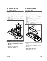
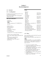
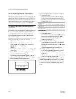
2-5. RM-BR300 Main Parts
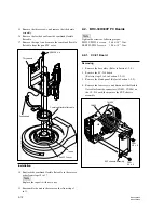
2-5-1. Joystick Controller
Removing
1.
Remove the outer (upper) assembly.
(Refer to steps 1 and 2 in Section 1-5-1.)
2.
Disconnect the harness from the connector CN5004 on
the MD-131 board.
3.
Remove the four screws, and remove the J sheet and
joystick controller.
Installation
4.
Reattach the joystick controller in the reverse order of
steps 2 and 3.
5.
Reattach the outer (upper) assembly.
(Refer to step 3 in Section 1-5-1.)
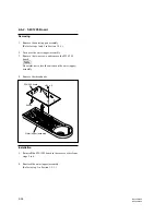
2-6. RM-BR300 PC Boards
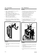
2-6-1. MD-131 Board
Removing
1.
Remove the outer (upper) assembly.
(Refer to steps 1 and 2 in Section 1-5-1.)
2.
Disconnect the harness from the connector CN5004 on
the MD-131 board.
3.
Remove the four screws, and remove the MD-131
board.
4.
Remove the slide knob and DC button.
n
When removing the MD-131 board, be careful not to
lose the slide knob and DC button.
Installation
5.
Reinstall the MD-131 board in the reverse order from
steps 2 to 4.
6.
Reattach the outer (upper) assembly.
(Refer to step 3 in Section 1-5-1.)


