9
BRC-300/300P
BRU-300/300P
Contents
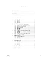
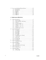
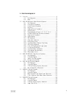
This service manual is organized by following sections.
Section 1
Service Overview
Explains the information that is required to service, (the locations of main part,
removal of cabinet, writing the firmware, service action after board replacement/
repair and part replacement, etc.).
Section 2
Replacement of Main Parts
Explains the replacement of mechanical parts, and circuit boards of each unit.
Section 3
Electrical Alignment
Explains the electrical alignment for the maintenance of each unit.
Section 4
Troubleshooting
Explains the measures against trouble.
Section 5
Circuit Description
Explains the circuit operation of the circuit boards installed in each unit.
Section 6
Spare Parts
Describes the exploded views, the mechanical parts list, and the electrical parts list.
Section 7
Semiconductor Pin Assignments
This section contains information on semiconductors used for each unit.
It includes a complete list of the semiconductors and their ID Nos. for retrieving
information on “Semiconductor Pin Assignments” CD-ROM, which is available
separately.
Please refer to this section together with the “Semiconductor Pin Assignments” CD-
ROM.
Information on the semiconductors not contained in the latest CD-ROM at the time
of issue of this manual, if any, is given in this section as well.
Section 8
Block Diagrams
Describes the overall block diagrams of each unit.
Section 9
Schematic Diagrams
Describes the schematic diagrams of the circuit boards installed in each unit and
frame wiring for each unit.
Section 10 Board Layouts
Describes the board layouts of the circuit boards installed in each unit.


