3-41
BRC-300/300P
BRU-300/300P
3-6. BRBK-302 Electrical Alignment
Oscilloscope
Frequency counter
Probe
S8001
3-6-3. VCO Free-running Frequency
Adjustment
Adjustment Procedure
1.
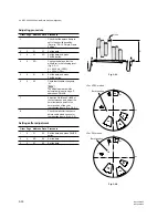
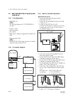
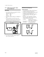
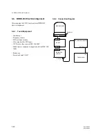
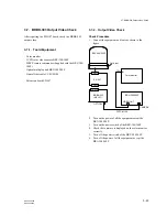
Connect the oscilloscope and the frequency counter as
shown in the figure.
2.
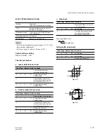
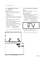
Set the switch S8001 on the SD-50 board as shown in
the figure.
3.
Turn on the power of all the equipment, and warm
them up for about 20 minutes.
The indicator D8001 on the SD-50 board will be lit.
4.
Perform the adjustment checking the value of the
frequency counter.
Test point:
TP8001/SD-50 board
GND: Body (shell part) of BNC
connector
Adjusting point:
1
RV8001/SD-50 board
Specification:
27000
±
27 kHz
5.
Turn off the power of the BRC-300/300P.
6.
Reset the switch S8001 on the SD-50 board as shown
in the figure.
7.
Perform “3-6-4. Output Video Check”.
S8001
SD-50 BOARD (A SIDE)
RV8001
TP8002
TP8001
D8001
S8001

