background image

WIRE, CABLE AND HOSE ROUTING 16-6 

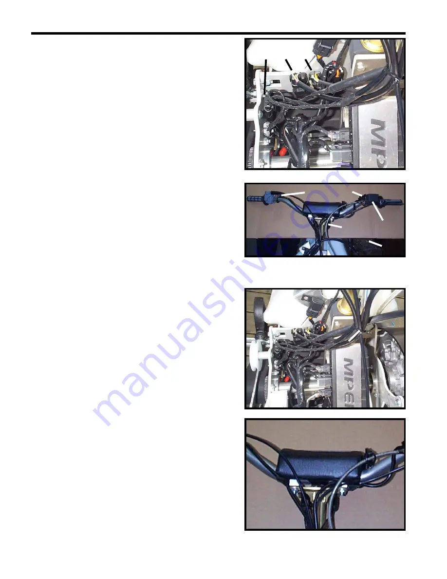
Handlebar-Mounted Devices/Switchgears 

1. Brake 

switch 


The 2-circuit connector from the brake switch (YL and 
YL/WT wires) connects to the 2-circuit connector on the 
main wiring harness (YL and WT wires). 

2. Dimmer 

switch 

The 3-circuit connector from the dimmer switch (GY, RD/YL 
and GY/BK wires) connects to the 3-circuit connector on the 
main wiring harness (GY, YL and VI/WT). 


3. Tether 

switch 

The 2-circuit connector from the tether switch (BK and 
BK/YL wires) connects to the 2-circuit connector on the 
main wiring harness (BK and BK/YL wires). 

4.   Emergency stop switch 

The 2-circuit connector from the emergency stop switch (BK 
and BK/YL wires) connects to the 2-circuit connector on the 
main wiring harness (BK and BK/YL wires). 

5.   Headlamp Connector 


Once all of the connectors are seated, group the handlebar 
accessory, headlamp and throttle cable together with a nylon tie 
wrap. MAKE SURE that this grouping does not affect the cycling 
of the throttle cable or the steering of the vehicle in any way.  


Place the emergency stop switch, the dimmer switch and the 
brake switch wires underneath the crashpad as shown at right. 


Tie wrap 

Summary of Contents for 600HO

Page 1: ...MY2004 Set up Service and Shop Manual SNOW HAWK 600HO...

Page 2: ...attention to particular instructions and procedures which if not followed to the letter could cause injury and even fatal accidents CAUTION This symbol is designed to call attention to particular ins...

Page 3: ...tor is running can be dangerous Injuries could result from contact with moving parts Make sure you turn off the motor before working on the vehicle WARNING Working on this vehicle without wearing the...

Page 4: ...nd P N 413 703 100 Loctite 271 10 ml High strength threadlocker P N 293 800 005 Loctite 243 10 ml Medium strength threadlocker P N 293 800 015 Sealing compound 30 ml P N 420 297 905 Loctite Primer 128...

Page 5: ...ctite 518 50 ml Gasket Paste P N 293 800 038 Loctite chisel 510g Gasket paint remover P N 420 899 763 Molykote PG 54 10g P N 420 899 763 Petamo Grease P N 420 899 271 Molykote G n plus 50g P N 711 297...

Page 6: ...etic injection oil Bombardier Formula XP S II 3 x 4 litres P N 293 600 046 Synthetic injection oil Bombardier Formula XP S II 12 x 1 litre P N 293 600 045 Pre mix oil 12 x 500ml P N 413 803 100 Premix...

Page 7: ...x 350 g Canada P N 413 711 600 USA P N 413 711 900 Synthetic Grease 400 g P N 413 711 500 LMZ Grease No 1 400 g P N 413 707 500 Molykote 111 50 g P N 413 707 000 Bombardier lube 12 x 14 oz P N 293 60...

Page 8: ...ompound 236 ml P N 293 800 070 Brake fluid SRF DOT 4 P N 293 600 063 Brake fluid GTLMA DOT 4 P N 293 600 062 Heavy Duty Cleaner 400 g P N 293 110 001 4 litres P N 293 110 002 Shock oil 32 oz P N 293 6...

Page 9: ...ipe sealant P N 293 800 018 Loctite 648 5 ml High temperature and strength retaining compound P N 413 711 400 Plastic and vinyl cleaner P N 413 711 200 Loctite Ultra Copper 80 ml High temperature RTV...

Page 10: ...SYSTEM ENGINE CYLINDERS HEAD BASE PRIMARY TRANSMISSION SYSTEM SECONDARY TRANSMISSION SYSTEM HYDRAULIC BRAKE SYSTEM FRONT FORK AND TWIN AXIS SKI REAR SUSPENSION SHOCKS AND TRACK CHASSIS AND STEERING E...

Page 11: ...ping in mind the speed of the vehicle the snow conditions and how quickly you want to change direction WARNING Some people enter a turn by stretching out a leg on the inside of the turn and letting th...

Page 12: ...off tether 5 Gas tank cap 6 Dimmer switch 7 Choke control 8 Emergency stop button 9 Temperature Light 10 Hood latches 4 11 Rear module latches 4 12 Bellypan latches 6 13 Kick stand 14 Headlight 15 Sto...

Page 13: ...s CAUTION A mixture in which the proportion of oil is too low will cause piston failure On the other hand a mixture in which the proportion of oil is too high will cause excessive carbon deposits that...

Page 14: ...rn to its original position as soon as it is released o Turn the twist throttle control a few times to make sure it functions properly The control must return automatically to the idle position as soo...

Page 15: ...contribute to a good break in On the other hand periods of long high acceleration sustained high speed and engine overheating are harmful during the break in period WARNING This vehicle is equipped w...

Page 16: ...check them regularly during this period REMOVAL OF THE BODY PANELS HOOD REAR MODULE AND BELLYPAN In order to work on the vehicle more easily and to access the anchor ties we suggest that you remove th...

Page 17: ...the sides of the belly pan towards the rear of the vehicle o De latch the four rubber latches on the bottom of the belly pan o Descend the belly pan to floor level most maintenance can be performed wi...

Page 18: ...imary and secondary clutch V V V C Primary clutch bolt V V Secondary clutch pre tension V A V A Secondary drive belt cog belt V V Cog sprockets V V Torque Limiter V V A Taper Locks V V Brake fluid V F...

Page 19: ...ore often under severe usage conditions Clean the filter in a solution containing a non flammable cleaning solvant such as hot soapy water Once dry apply some light engine to the filters to prevent th...

Page 20: ...he system to detect any leak or abnormality in the gasket material Cooling system Inspect the coolant level in the coolant reservoir located on the MAG side of the vehicle If the coolant level is belo...

Page 21: ...Chapter 8 Primary Transmission System Pre tension of the secondary clutch spring For more information refer to Chapter 8 Primary Transmission System Primary transmission belt Examine the belt Make sur...

Page 22: ...e instructions found in Chapter 9 Secondary Transmission System Cog Sprockets Check the appearance of the cog sprockets Make sure all the sprockets are there and are free of any accumulated dirt Clean...

Page 23: ...when the vehicle is stored in a heated garage A visual inspection of the fork legs can reveal oil leaks that might indicate broken main seals If excessive oil is presest on the lower fork leg a seal...

Page 24: ...around the shock guards for the presence of oil leaks Shock oil must be replaced once a year Refer to Chapter 12 Rear suspension and Track CAUTION It is advisable to change the shock fluid when prepa...

Page 25: ...PERIODIC MAINTENANCE 2 8 2 8 CHASSIS AND STEERING Handlebar mounting bolts Verify and adjust the torque to 36 5 N m 3 7 kg m 27 lbf ft following a criss cross order...

Page 26: ...m Therefore bolts must be checked and tightened as need be When doing this refer to the Torque Table at the end of this section 2 9 ELECTRICAL SYSTEM Spark plug Check the general condition of the plug...

Page 27: ...uate Refer to the NGK codification on the next page Porcelain Colour Probable Cause Plug Temperature rating is too high Plug gap too wide Air Fuel mixture too lean Stale gasoline Plug temperature rati...

Page 28: ...PERIODIC MAINTENANCE 2 11 Symbols used on the NGK spark plugs...

Page 29: ...se refer to the following table N m kg m lbf ft lbf in N m kg m lbf ft lbf in 6 10 1 7 84 15 1 5 11 132 8 25 2 5 18 216 36 3 6 27 324 10 49 4 9 36 432 72 7 2 53 636 12 85 8 5 63 756 125 12 5 92 1104 G...

Page 30: ...FUEL SYSTEM 3 1 19 22 32 30 32 31 21 18 19 34 20 24 33 26 19 23 24 25 22 6 27 29 28 7 1 10 11 11 15 9 8 12 13 9 8 14 16 3 2 4 35 5 17 35 FUEL SYSTEM...

Page 31: ...0054 1 Twist throttle 17 24 1101 1 Grips pair 18 403 901 811 1 Fuel pump 19 414 420 700 3 Spring clamp green 20 14 349 1 Tubing 21 415 080 200 1 1 Hose pump carburetor 22 414 415 200 2 Spring clamp re...

Page 32: ...FUEL SYSTEM 3 3 CARBURET0RS TM 40...

Page 33: ...2 O ring 18 404 161 933 4 Screw 19 404 161 932 2 Float 20 404 161 960 2 Float Body 21 707 200 027 1 E ring 22 404 162 007 4 Plate 23 404 162 008 2 Holder 24 404 161 928 2 Screw 25 404 162 009 2 Lever...

Page 34: ...55 404 161 903 2 Screw 56 404 162 000 1 Bracket 57 404 161 901 1 Starter lever 58 404 161 899 2 Cap 59 404 161 898 2 Adjuster 60 404 161 897 2 Spring 61 404 161 896 2 Washer 62 404 161 895 2 Packing 6...

Page 35: ...tings of either Remove dual carburetor assembly pinch and disconnect fuel line Take care to recuperate fuel WARNING Fuel is flammable and explosive under certain conditions Always wipe off any fuel or...

Page 36: ...ive Inspect the condition of the tip of the fuel inlet valve If the tip is worn replace both the valve and its seat NOTICE Install only a snowmobile carburetor inlet valve as it is designed to functio...

Page 37: ...ed to suit temperature and or altitude changes A service bulletin will give information about calibration according to altitude and temperature Main jet 5 may be removed without removing float bowl 20...

Page 38: ...care not to loose plastic washer 9 under needle circlip 10 2 INTAKE SPICKET Unscrew throttle slide cover screws 70 Open throttle 3 4 wide and hold it there Lift throttle slide covers bottom first unt...

Page 39: ...CREW ADJUSTMENT Completely close the pilot screw until a slight seating resistance is felt then back off as specified Turning screw clockwise leans mixture and conversely turning it counter clockwise...

Page 40: ...retor proceed using the synchronization screw Use the same drill bit used for the PTO carburetor to measure throttle slide height Turn synchronization screw to adjust 1 PTO carburetor adjusted first 2...

Page 41: ...k to the lower shaft at the middle bottom of the carburetor assembly THROTTLE CABLE ADJUSTMENT Adjust throttle cable as per following procedure Loosen throttle cable housing adjusting and locking nuts...

Page 42: ...s position As a confirmation the gap between the stopper and the bracket should be within 0 and 0 5 mm 0 and 1 64 in A Within 0 and 0 5 mm 0 and 1 64 in Idle Speed Final Adjustment Start engine and al...

Page 43: ...ply pressure and vacuum with pump of leak test kit The inlet valve should re lease with pressure and hold under vacuum Repeat the same procedure at the outlet nipple This time the outlet valve should...

Page 44: ...d in general purpose solvent and dried with compressed air WARNING Solvent with a low flash point such as gasoline naphtha benzol etc should not be used as each is flammable and explosive Inspect diap...

Page 45: ...Remove the hose clamp retaining the exhaust pipe as well as the two forward brackets P N s SH032L and SH032R o Remove the four springs that hold the exhaust pipe tight against the Y manifold o Remove...

Page 46: ...it NOTICE Use a crate or box to support to support the vehicle just under the drive sprockets when removing the fork Recoil Starter o Using a flat head screwdriver push the knot out of the recess in t...

Page 47: ...ry clutch to the jackshaft and then slide the secondary off the jackshaft at the same time removing the drive belt o Using the primary clutch holder tool P N 529 027 600 remove the primary clutch bolt...

Page 48: ...intake boots and then remove the carburetors completely as a pair Engine Connector o Cut the tie wrap and disconnect the two place housing that connects the Crank Position Sensor CPS to the wiring har...

Page 49: ...the four place housing yellow yellow and yellow wires and the two place housing green and black wires that is next to the four place housing o Unplug the two wires from the two temperature sensors loc...

Page 50: ...cable to the oil reservoir hose Cooling System o Loosen the hose clamp that holds the forward cooling hose to the water pump housing inlet at the front of the engine With a bucket below this point let...

Page 51: ...ne to the inlet of the tunnel mounted heat exchangers and should remain connected to the engine when removing o Now that all of the peripheral equipment has been disconnected unscrew and remove the 4...

Page 52: ...e belt o Ensure that each cable wire and hose is properly connected and its original routing is used See Chapter 17 Wire Cable and Hose Routing for more details o Ensure that each coolant line is re i...

Page 53: ...REWIND STARTER 5 1 REWIND STARTER...

Page 54: ...pe sheave 6 412500200 1 Starter rope 2200mm 7 420852297 1 Pawl 8 420852305 1 Pawl lock 9 420847925 1 Stage sleeve 10 420250400 1 O ring 11 420852520 1 Lock ring 12 420845560 1 Locking element 13 1 Pos...

Page 55: ...lled If not disassemble rewind starter clean and check for damaged plastic parts Replace as required lubricate reassemble and recheck Always replace O ring 10 every time rewind starter is disassemble...

Page 56: ...spring preload o Cut locking element 12 and discard Remove lock ring 11 O ring 10 stepped sleeve 9 Pawl lock 8 and Pawl 7 o Remove sheave 5 from starter housing 3 Hold the spring with a screwdriver o...

Page 57: ...on o To install rope 6 insert rope into sheave 5 orifice and lock it by making a knot leaving behind a free portion of about 25 mm in length Fuse rope end with a lit match and insert it into sheave o...

Page 58: ...O ring 10 and lock ring 11 whit Molykote PG 54 Install over pawl lock 1 Stepped sleeve 2 O ring 3 Lock ring o Install the locking element nut 12 INSTALLATION o Fuse rope end with a lit match o Thread...

Page 59: ...COOLING SYSTEM 6 1 COOLING SYSTEM 1 2 3 4 5 6 7 8 9 10 11 12 12 12 12 12 12 12 12 12...

Page 60: ...lant tube 3 7 SH 095 1 Coolant tube 1 8 SH 096 1 Coolant tube 5 9 SH 097 1 Coolant tube 2 10 1 Overflow tube 11 414554800 1 Spring clamp black 12 408800400 10 Hose clamp geared 278001016 1 Temperature...

Page 61: ...76 on the overflow hose Using pump also included in the kit and pressurize the entire system through the coolant reservoir to 100 kPa 15 PSI o Check all hoses and cylinder base for coolant leaks Spray...

Page 62: ...nction is to give faster warm up of the engine by controlling a circuit water pump engine coolant tank This is done by bypassing the heat exchanger radiator circuit and using what it called a short ci...

Page 63: ...g tank to avoid emptying o Install pressure cap o Lift rear of vehicle and support it safely o Blip the throttle 3 4 times to bring engine speed to 7000 RPM o Apply the brake to stop the track o Lower...

Page 64: ...HEAD BASE 7 1 ENGINE BOTTOM END 33 1 12 2 3 4 5 6 7 8 8 9 10 11 12 13 13 14 20 15 18 17 16 19 23 24 22 20 21 25 26 28 29 30 31 32 34 35 36 37 38 29 N m 21 5 lbf ft 3 0 kg m 258 lbf in 39 40 41 42 43 4...

Page 65: ...Assy 15 1 Step Collar 16 420230195 1 Oil Seal 17 420232100 1 Ball Bearing 18 420650370 1 Oil Seal 19 420950890 2 O Ring 20 1 Water Pump Shaft 21 420840511 2 Socket Head Screw M5 x 16 22 420227945 1 W...

Page 66: ...20874370 1 Reducer fitting 41 420956239 Oil Line 42 420951260 1 Clamp 43 420951240 1 Clamp 44 420960279 1 Cap 45 47 420956240 1 Oil Reservoir Assy 46 420850350 1 Rubber Gasket 47 420956250 1 Oil Cap 4...

Page 67: ...ENGINE CYLINDERS HEAD BASE 7 4 ENGINE CRANKSHAFT AND PISTONS...

Page 68: ...n Assy 71 89mm 14 420815290 2 Semi trapez ring 15 420916410 2 Gudgeon pin 16 420845106 4 Piston Circlip 17 420832575 1 Brg 6207 18 420931455 2 Oil Seal 19 420834355 1 Central Gear 15 teeth 20 42081970...

Page 69: ...ENGINE CYLINDERS HEAD BASE 7 6 ENGINE TOP END...

Page 70: ...ew 16 420241270 4 Screw M5 X 25 17 420640524 4 Hex collar screw M10 x 80 18 420640534 4 Hex collar screw M10 x 120 19 420931590 2 Rubber Ring Seal 20 293300026 2 O ring 21 420613700 1 Cylinder Head Si...

Page 71: ...Descriptions 39 420941925 12 Screw M5 x 16 40 420850552 2 Gasket 41 420673070 1 Exhaust Manifold 42 420889920 1 Engine Gasket Set 43 420889925 1 Cyliinder Gasket Set 44 420297906 30mL Sealing Compoun...

Page 72: ...ers AUS over an arrow on the piston dome must be visible after cleaning o Clean the piston ring groove with a groove cleaner tool or with a piece of broken ring DISASSEMBLY RAVE System NOTICE RAVE sta...

Page 73: ...piston pin puller P N 529 035 503 along with 20 mm sleeve kit P N 529 035 542 Use also a locating sleeve NOTICE The locating sleeve is the same that contains new cageless bearing Insert piston pin pu...

Page 74: ...nscrewing puller until shouldered sleeve end is flush with thrust washer of piston pin bearing Remove puller Pull out shouldered sleeve carefully Remove piston from connecting rod Install locating sle...

Page 75: ...ystem Install RAVE valve noting which is the top side when it was removed Tighten red cap no 15 screw to bottom 2 13 Cylinder and Piston Before inserting piston in cylinder lubricate the cylinder with...

Page 76: ...gun before piston installation to make the insertion of the pin much easier CAUTION Piston temperature must not exceed 46 C 115 F Never use direct flame to heat the piston and never freeze the pin At...

Page 77: ...t 6 o clock as illustrated Use appropriate piston circlip installer Use circlip installer P N 529 035 686 to install new mono hook circlips no 16 Insert circlip into support so that when installed in...

Page 78: ...crankcase mating surface with Loctite 518 P N 293800038 Choose the right gasket thickness according to combustion chamber volume Refer to LEAK TEST AND ENGINE DIMENSION MEASUREMENT Install it on the c...

Page 79: ...ing reed block With blade stopper no 37 removed check reed valve for proper tightness There must not be any play between blade and valve body when exerting a finger pressure on blade at blade stopper...

Page 80: ...e chassis to carry out the following operations See Chapter 4 Engine Removal for details CLEANING o Discard all gaskets and O rings o Clean all metal components in a non ferrous metal cleaner Use gask...

Page 81: ...75 C 167 F This will expand the bearing and ease installation Some bearings must be lubricated with Isoflex grease P N 293 550 021 CAUTION Use only the recommended Isoflex grease Make sure not to push...

Page 82: ...grease already applied At crankshaft installation position drive pins as illustrated 1 Position pins Pour 50 mL 2 U S oz of injection oil in the pan under central gear to lubricate pump gearing as pe...

Page 83: ...d P N 420 297 906 Make sure surfaces are perfectly clean and degreased before applying sealing compound Spread a seam of 1 2 mm 1 16 in maximum in diameter on the surface of lower crankcase half As fa...

Page 84: ...ng first screw bolts up to 60 of the final torque 18 N m 13 5 lbf ft for most of the bolts then tighten to the required torque i e 29 N m 21 lbf ft A Torque bolts 1 through 16 to 29 N m 21 lbf ft B To...

Page 85: ...urize engine to 34 kPa 5 PSI Do not exceed this pressure 8 Engine must stand this pressure during 3 minutes If pressure drops before 3 minutes check tester kit by spraying a soapy solution on pump cyl...

Page 86: ...nt pump housing bleed screws plugs 2 Remove cooling system cap Check for air bubbles in antifreeze It indicates defective cylinder head O ring or cylinder base gasket 3 Remove drive pulley then check...

Page 87: ...il pump side which is blocked off on the Snow Hawk 600HO Check this mounting area and the two mounting bolts for leaks 3 If leak still persists it indicates a defective casting somewhere in the engine...

Page 88: ...ENGINE CYLINDERS HEAD BASE 7 25 CHECK FOR OIL LEAKS AROUND OIL PUMP BLOCK OFF PLATE OIL LEAKING FROM AROUND EDGES OF BLOCK OFF PLATE REPLACE GASKET...

Page 89: ...ENGINE CYLINDERS HEAD BASE 7 26...

Page 90: ...mpare cylinder diameter 16 mm 5 8 in from top of cylinder to just below its intake port area If the difference exceeds the specified dimension the cylinder should be rebored and honed or should be rep...

Page 91: ...nder sleeve port openings 1 Piston pin position 2 Measures to be compared A 16 mm 5 8 in COMBUSTION CHAMBER VOLUME MEASUREMENT The combustion chamber volume is the region in the cylinder head above th...

Page 92: ...op spark plug hole Top of spark plug hole NOTICE The liquid level in cylinder must not drop for a few seconds after filling If so there is a leak between piston and cylinder The recorded volume would...

Page 93: ...rest USED PISTON MEASUREMENT Note the measurement on the piston dome 1 Piston dome 2 Piston measurement Using a micrometer measure piston skirt at 15 mm 590 in perpendicularly 90 to piston pin 1 Measu...

Page 94: ...he measurement on the piston dome 1 Piston dome 2 Piston measurement Adjust and lock a micrometer to the specified value on the piston dome 1 Micrometer set to the piston dimension With the micrometer...

Page 95: ...5 8 in Read the measurement on the cylinder bore gauge The result is the exact piston cylinder wall clearance If clearance exceeds specified tolerance replace cylinder NOTICE Make sure the cylinder bo...

Page 96: ...ces 1 Transfer port 2 Intake port CRANKSHAFT DEFLECTION Crankshaft deflection is measured with a dial indicator Measuring in crankcase First check deflection with crankshaft in crankcase If deflection...

Page 97: ...ed between centers of a lathe If the deflection exceeds the specified tolerance crankshaft should be repaired or replaced Using a feeler gauge measure distance between thrust washer and crankshaft cou...

Page 98: ...all a TDC gauge P N 414 104 700 in spark plug hole on MAG side o Bring MAG piston to top dead center o Rotate degree wheel not crankshaft so that 360 mark aligns with center of crankcase Scribe a mark...

Page 99: ...PRIMARY TRANSMISSION SYSTEM 8 1 PRIMARY TRANSMISSION SYSTEM PRIMARY CLUTCH 10 N m 1 kg m 7 4 lbf ft 125 lbf in 90 N m 9 2 kg m 66 lbf ft 797 lbf in...

Page 100: ...2018 1 Spring Compression Limiter 5 0151 1007 1 Spring 6 0440 0005 1 Spring Cover 7 420 2453 700 3 Lock Washer 8 0080 0021 3 Socket Head Screw 9 0130 3006 3 Slider Block 10 X 81 3 15 Mass small 11 01...

Page 101: ...PRIMARY TRANSMISSION SYSTEM 8 3 9 15 7 10 6 4 3 5 8 11 2 14 13 12 16 17 19 18 25 N m 18 4 lbf ft 2 5 kg m 221 lbf in 16 21 PRIMARY TRANSMISSION SYSTEM SECONDARY CLUTCH 20...

Page 102: ...417 1264 22 1 Helix 50 o 44 o 8 414 8208 00 1 Key 9 371 9031 00 1 Retaining Ring 10 414 5589 00 1 Preload Spring beige 11 504 1419 00 1 Washer 12 223 5630 65 3 Bolt M6x 30 13 228 0610 45 3 Nut M6 14...

Page 103: ...n in the procedure and respect the assembly tolerances REMOVAL PRIMARY CLUTCH o Use the primary clutch tool P N 529027600 to hold the clutch in place o Remove the mounting bolt No 18 o Insert the prim...

Page 104: ...tions with their curved end facing the cover o Be careful to place the arrow of the cap in line with the mark on the sliding sheave and that of the fixed pulley o Tighten cover nut No 16 to 128 N m 95...

Page 105: ...is pin in the groove of the key 1 WARNING The secondary clutch cam is equipped with a spring Use the tool indicated above CLEANING Large bushing and small bushing During the break in period about 10 h...

Page 106: ...der blocks o Install an application plate P N 529031103 inside the sliding sheave o Place the extractor P N 529031102 under the bushing o Install the extractor screw head in a vise o Turn the sheave m...

Page 107: ...uniform pressure on the cam To re assemble the parts of the secondary carry out the operations for disassembly in the reverse order Cam o Coat the inside of the cam with anti seize compound INSTALLAT...

Page 108: ...o Take a first measurement when the sliding half pulley begins to turn Let it turn 10 mm 3 8 in Hold the spring scale in this position Gently slacken the tension on the spring scale and take the seco...

Page 109: ...icle and that the tension and alignment of the track have been checked Always check the adjustment of the clutches whenever the suspension is adjusted WARNING If the alignment procedure for the clutch...

Page 110: ...irection MEASURING THE DEFLECTION OF THE DRIVE BELT NOTICE The deflection must be measured each time a new drive belt is installed NOTICE To get a precise measurement when verifying the deflection of...

Page 111: ...uge P N 414348200 to verify the tension of the drive belt 1 Lower ring 2 Upper ring 3 Force 4 Deflection o Slide the lower ring of the deflection scale to the required measurement o Slide the upper ri...

Page 112: ...ockwise 1 Allen screw and locknut NOTICE Turn the Allen screws a quarter turn at a time and then turn the secondary clutch to allow the drive belt to take its place in the pulley Verify the deflection...

Page 113: ...SECONDARY TRANSMISSION SYSTEM 9 1 12 10 3 5 11 11 1 4 6 2 7 6 8 9 SECONDARY TRANSMISSION SYSTEM 13 14 N m 125 lbf in Follow the suggested sequence 14 N m 125 lbf in Follow the suggested sequence 14 14...

Page 114: ...1 Retaining ring 6 6004 2RS KML 2 Roller bearing tensioner 7 409 716 1 Washer 8 441 1 1 Split spring lock washer 9 20238P 1 Hexagon head cap screw M10 x 1 5 x 60MM 10 90974 A116 1 Sliding T nut 11 121...

Page 115: ...SECONDARY TRANSMISSION SYSTEM 9 3 7 6x 3 4 6 8 2x 5 1 5 8 2x 6 4 2 TORQUE LIMITER SYSTEM 6 N m 55 lbs in 10 N m 89 lbs in 10 N m 89 lbs in 9 9...

Page 116: ...threaded disk 4 TL 004 2 Outside pressure plate 5 TL 005 2 Inside pressure plate 6 6525K1 O D 5 2 Wearing pad 7 21653P 6 Socket head cap screw M8 x 1 25 x 30MM 8 22097P 4 Flat head socket cap screw M...

Page 117: ...move the two setscrews that hold the taper lock and the 28 tooth upper drive sprocket in place Position 1 Using a punch hit the taper lock 2 3 times in the shaded zone shown at right Position 5 to loo...

Page 118: ...Loctite 243 must be used for both installation setscrews to prevent them from loosening under use Failure to do so could result in personal injury Hand tighten the tensioner sprocket bolt Ref No 9 in...

Page 119: ...ive dry surface cracking of the rubber in the cog belt If excessive surface cracks are present replace belt o Check that the secondary transmission system is dry and free of dirt grime or debris If ne...

Page 120: ...ponents should be clean before reassembly The parts can be cleaned using brake cleaner INSPECTION NOTICE Because so much dirt and dust accumulates inside the torque limiter it should be periodically c...

Page 121: ...INSTALLATION Install the torque limiter as described in the previous section on installation of the secondary drive cog belt o Lift up and immobilize the rear of the vehicle and place it on a mechani...

Page 122: ...HYDRAULIC BRAKE SYSTEM 10 1 12 11 11 14 3 1 11 7 6 7 6 2 15 5x 4 5 10 5x 9 8 8 HYDRAULIC BRAKE SYSTEM 25 N m 220 lbf in 14 N m 125 lbf in 16 14 N m 125 lbf in...

Page 123: ...8 45 2 Hexagon head cap screw M8 x 1 25 x 45MM 8 23164 2 Nylon nut M8 x 1 25 9 1215X30 1 Taper lock c w setscrews 10 22204P 5 Button head cap screw M6 x 1 0 x 20MM 11 06 2196 13 2 Copper washer 12 06...

Page 124: ...ove the bolt from inside the tunnel with a socket and ratchet Loosen the other upper bolt holding the caliper tight to the chassis as well then swing the caliper up and clear of the disc Re tighten th...

Page 125: ...emove the clip at the end of the pin shown in the picture on page 10 3 of this chapter o Using a steel punch and a hammer push the pin completely out of the brake caliper casting Be sure to push the p...

Page 126: ...sufficient amount of brake fluid in the reservoir at all times to avoid the creation of air bubbles in the system If air should become trapped in the system follow the procedure outlined below Pump t...

Page 127: ...FRONT FORK AND TWIN AXIS SKI 11 1 FRONT FORK...

Page 128: ...49350102 2 Cartridge 2 849310511 2 Inner Tube 3 849340059 2 Fork Seal and Bushing Kit 4 849311568 2 Top Cap Assy 5 849350103 2 Compression valve Assy 6 949409760 2 Outer Tube 7 949603733 2 Lower Sprin...

Page 129: ...FRONT FORK AND TWIN AXIS SKI 11 3 FRONT FORK ASSEMBLY...

Page 130: ...30 8 23162F 8 Flanged locknut M6 9 SH 051 2 Steel T Bushing 10 084 6 2 4 Button head bolt M6x20 11 23162 2 Locknut M6 12 20169P 2 Hex head bolt M6x65 13 SH 060 1 End shaft bushing 14 442 12 1 1 2 Spri...

Page 131: ...FRONT FORK AND TWIN AXIS SKI 11 5 TWIN AXIS SKI ASSEMBLY 10 9 8 10 9 8 7 3 10 11 12 12 12 12 2 6 5 5 6 1 4 4...

Page 132: ...8310120065ELZN 2 Carriage Bolt M12x65 6 P05000050095A 2 Gold polyurethane bushing 7 20279P 1 Hex head bolt M12x80 8 P05000050090A 2 Red polyurethane bushing 9 341 109P 2 7 16 washer 10 23167F 3 Flange...

Page 133: ...be more responsive and have a quicker turning feel o The stock settings have 5 8 of thread protruding above the end of the locknuts which is great for a novice rider and is near the minimum preload se...

Page 134: ...d Use a mild detergent or an automobile cleaning product to dislodge any dirt CAUTION An inadequate dismantling of the fork leg top cap may damage the rebound adjustment needle resulting in a malfunct...

Page 135: ...rned upside down the push rod the needle and the return spring will fall from the piston rod It is possible to collect them by turning the strut over slowly and keeping a finger near the tip of the pi...

Page 136: ...gs at one end provided with the maintenance tool kit into the cartridge head NOTICE Before unscrewing the cartridge make sure the special tool T is well fitted into the socket in the cartridge head o...

Page 137: ...oving the dust seal o Use a flat screwdriver to remove the dust seal o Remove the stop ring o With a few sharp blows pull the outer tube P out to separate it from the inner tube A o The oil seal T the...

Page 138: ...end of the strut with a band of adhesive tape so that the seals will not be damaged by the sharp edge o Make sure the bushings S R are well inserted in their respective positions by using the special...

Page 139: ...l tool W to insert the washer Q and then the oil seal T o Re install the stop ring O o Re install the dust seal M o Using a 14 mm allen key and the special tool T re install the cartridge L the compre...

Page 140: ...rtical position fully compressed and fill it with fork fluid up to 50 mm 2 in from the top of the outer tube Recommended fluid Cartridge fork fluid S A E 15W o Move the piston rod in and out in a seri...

Page 141: ...recommended level CAUTION The fluid level can be modified but must remain between 85 mm and 120 mm o Insert the needle return spring the needle and the push rod o Install the spring F inside the stru...

Page 142: ...ue wrench and the special tool to adjust the torque to 18 20 N m 1 8 2 0 kg m 13 2 14 75 lbf in o Screw the strut top cap onto o the outer tube Again use the torque wrench and the special tool to adju...

Page 143: ...ound Using a screwdriver it is possible to choose a precise setting for the speed of rebound from a range of 28 positions depending on the conditions of the terrain and the purpose for which the vehic...

Page 144: ...8 8 40 39 1 2 3 48 23 20 66 MAG 9 9 23 49 16 38 9 71 11 3 13 12 3 14 51 57 53 38 56 15 52 1 52 10 38 51 1 45 65 44 57 3 57 63 48 2 1 9 34 60 3 34 2 55 3 1 35 34 35 46 35 36 44 47 42 46 22 46 45 43 39...

Page 145: ...REAR SUSPENSION SHOCKS AND TRACK 12 2 REAR SHOCK 53 67 68 69 70...

Page 146: ...REAR SUSPENSION SHOCKS AND TRACK 12 3 MIDDLE SHOCK 54 73 67 70...

Page 147: ...asher M5 19 570 063 000 2 Rubber stopper 20 825 8CP 12 Hexagon head cap screw M8 x 1 25 x 25MM 21 22205P 2 Button head socket cap screw M6 x 1 0 x 25MM 22 21085P 4 Washer M6 23 517 078 700 8 Limiter s...

Page 148: ...shock assy 55 014 00 2 Adaptor 56 SH 418 2 Upper shaft spacer 57 062 01 6 Upper shock eye bushing 58 SH 419 2 Spacer 59 018 00 2 Nylotron shim 60 RD0171 2 100mm idler wheel assy plastic 61 SH 420 1 U...

Page 149: ...REAR SUSPENSION SHOCKS AND TRACK 12 6 SHOCK EXPLODED VIEW 11 10 11 9 2 12 13 7 6 8 1 5 3 4...

Page 150: ...3 1 Floating piston 4 11301 03006 1 O ring 5 11301 03805 1 Piston bushing 6 11302 09919 1 Compressed air valve 7 11201 90604 1 Screw 8 11301 03021 1 O ring 9 11201 92151 1 Label 10 11301 91030 1 Colla...

Page 151: ...hen the adjustment is finished tighten the jam nut 1 once more 1 Jam nut 2 Spring adjustment ring 3 Special tool Rear spring preload The adjustment of the rear spring makes it possible to stiffen the...

Page 152: ...d Remove the shock absorber spring by unscrewing the pre load collar and jam nut then by removing the spring retainer hat To carry out these operations use tool P N 861 7439 00 Install the shock absor...

Page 153: ...t the floating piston from the body of the shock absorber Cover the opening of the shock absorber with a cloth to catch the floating piston Make sure there is enough space in the cloth for the piston...

Page 154: ...there is a leak in the ring seal it will be necessary to measure the camber of the rod which must not exceed 0 025 mm 001 in Once the new shims or the replacement shims have been selected reassemble e...

Page 155: ...r of grooves varies between 0 2 4 and 6 according to the rapidity of the rebound These grooves offer variations in the damping in relation to the shims COMPRESSION When adjusting the shock absorber to...

Page 156: ...ibrating the shock absorber so that there is not enough damping means the damping will either be insufficient or badly controlled In such a case the shock absorber moves up and down almost without any...

Page 157: ...g seal use a ring seal guide P N 529 0265 00 to guide the ring seal over the shock absorber rod Lubricate the guide before using it CAUTION The ring seal will be damaged if the guide is not used Reass...

Page 158: ...through the hole in the needle valve will push the piston up WARNING Be very careful when using compressed air Cover the opening in the shock absorber with a cloth to reduce any risk of injury WARNIN...

Page 159: ...n It might be necessary to jiggle the rod slightly to make it easier to place the piston in the bore of the body of the shock absorber Gently insert the piston into the body of the shock absorber A sl...

Page 160: ...itrogen This pressure will re establish the shock absorber pressure at its optimum level CAUTION Do not exceed the recommended pressure WARNING Always wear safety glasses when working with high pressu...

Page 161: ...ick as one thick shim but offer less resistance than the latter Refer to the table SHIM EQUIVALENCE FOR THE SAME DIAMETER as illustrated in this section o When stacking shims for rebound always use sh...

Page 162: ...is recommended that the following be checked o The alignment of the track 1 Guides 2 Hyfax slides 3 Equal distance o Track tension The track must have a free deflection of about 40 mm 1 just below th...

Page 163: ...44 20 78 78 78 78 78 78 99 99 99 99 117 20 113 113 114 114 99 99 99 39 39 99 99 119 112 114 114 113 117 113 78 78 78 78 78 78 19 78 112 97 97 39 119 78 78 108 79 79 108 79 47 86 88 89 22 78 78 46 21...

Page 164: ...8 10 96 101 99 101 48 38 99 99 37 37 99 99 102 103 53 108 12 100 52 52 51 51 50 49 50 49 99 99 104 18 105 108 14 108 16 108 108 15 15 32 32 111 78 86 86 115 116 79 119 107 1 55 54 79 79 13 24 86 79 38...

Page 165: ...8 6 98 98 96 36 36 37 34 33 33 35 101 99 11 108 111 108 32 32 78 108 16 109 6x 15 15 56 99 108 14 23 86 13 27 25 28 26 29 31 30 79 79 4 38 118 110 17 116 115 86 86 79 119 119 108 107 105 6x 38 100 106...

Page 166: ...HASSIS AND STEERING SYSTEM 13 4 63 65 62 58 64 4x 60 57 59 85 61 66 67 81 84 80 83 82 76 76 73 72 79 79 77 4x 69 69 69 69 68 86 86 74 87 70 71 78 4x 70 71 85 70 70 71 71 75 CHASSIS AND STEERING SYSTEM...

Page 167: ...CHASSIS AND STEERING SYSTEM 13 5 CHASSIS AND STEERING SYSTEM 90 4x 91 4x 92 4x 92 4x 93 4x 94 4x 95 4x 46...

Page 168: ...module front bungee hook 19 SH 038 1 Front chassis spacer 20 SH 020 2 Long chassis spacer 21 SH 021 1 Short chassis spacer 22 SH 120 1 Carburator support 23 SH11 SAG 1 Left peg PTO 24 SH11 SAD 1 Righ...

Page 169: ...63 SH 066 2 Fork bushing 64 21655P 8 Socket head screw M8 x 1 25 x 40MM 65 23166 2 Nylon nut M10 x 1 5 66 503 183 300 2 Washer 10MM sp cial 67 20237P 2 Hexagon head cap screw M10 x 1 5 x 55MM 68 4462...

Page 170: ...x 1 25 x 25MM 101 22216P 4 Button head socket cap screw M8 x 1 25 x 30MM 102 336 103 1 Hexagon flange stove nut 5 16 103 2946 1 Nylon flange nut 5 16 18 104 22205P 2 Button head socket cap screw M6 x...

Page 171: ...L SH600D10 1 MAG HOOD HAWK HEAD SH600D11 1 PTO HOOD HAWK HEAD SH600D12 1 HOOD AD BOIVIN LOGO SH600D13 2 HOOD SNOW DECAL SH600D14 1 MAG HOOD NOSE DECAL SH600D15 1 PTO HOOD NOSE DECAL 5937 6 HEAD LIGHT...

Page 172: ...13 1 SMALL BRAKE GRILL SH 115 1 MAG SIDE GRILL NOIR SH 133 1 TOOL POCKET 600HO 1661 0619 4 3 16 ALUMINUM POP RIVET 341 102P 4 3 16 POP RIVET BACKING PLT SH 121 1 BELLYPAN MAG SIDE HEAT SHIELD PIPE STI...

Page 173: ...EAR LAMP MODEL 218 STOP TAIL 12V 284118 4 RUBBER HOOK BUNGEE 169 113 2 PUSH NUT 176 115 2 WELL NUT M6 SEAT 333 105 4 ELASTIC HEX NUT 1 4 SEAT BASE 341 102P 4 3 16 POP RIVET BACKING PLT BUNGEES 341 103...

Page 174: ...MP 341 102P 10 3 16 POP RIVET BACKING PLT ADB 101 1 BLACK TUNNEL COVER 513032979 2 SPRING CLAMP light green Pump 2 adaptor 513033022 0 2 RUBBER HOSE Pump 2 adaptor 403 901 811 1 FUEL PUMP 600HO 420 87...

Page 175: ...ELECTRICAL SYSTEM 14 1 CDI SYSTEM 11 12 13 14 15 16 17 18 19 21 22 23 20 23 27 N m 20 lbf ft 2 75 kg m 240 lbf in 243 648 Sikaflex Black 221 P N 293530011 243 22 N m 16 lbf ft 2 25 kg m 192 lbf in 4...

Page 176: ...w M6x30 6 420640321 2 Screw M5x16 7 420866756 1 Counter Weight 8 420852532 1 Starting Pulley 9 420945752 1 Lock Washer 8mm 10 207182044 1 Hex Head Screw M8x20 11 512059552 2 BR9ECS Spark Plug 12 2 Spa...

Page 177: ...ELECTRICAL SYSTEM 14 3 WIRING DIAGRAM...

Page 178: ...in P N 515175665 278000632 10 Female Terminal used in Deutsch connectors 515175670 1 Female Housing 2 circuit MPEM Deutsch 515175673 1 Female Housing 6 circuit MPEM Deutsch 409209900 1 Female Housing...

Page 179: ...wheel To gain access to magneto assembly remove the following parts o All body panels o rewind starter o starting pulley no 8 To remove magneto flywheel retaining nut on the end of the crankshaft not...

Page 180: ...g o Remove retaining screws no 6 o Remove trigger coil and carefully pull wires o Install new trigger coil and other parts removed ASSEMBLY 2 Stator o Position stator No 2 at right so that its wire pr...

Page 181: ...Engine break in retard timing for the Snow Hawk 600HO is as follows the first hour of operation TYPICAL 1 TDC gauge on MAG side 2 MAG side piston at TDC NOTICE Between 3000 and 4000 RPM the spark adva...

Page 182: ...y Snow Hawk you can use the upper threaded hole in the crank case as a mounting position indicated by the white arrow o With the TDC gauge indicating specified timing shown at right scribe a mark on t...

Page 183: ...the timing is retarded or advanced Tolerance is 1 Changing Timing As a Snow Hawk dealer there is no immediate way to alter the MPEM s internal timing settings other than to send the unit back to us an...

Page 184: ...proximately 20 C 68 F room temperature otherwise the readings could be distorted Analysis of Readings Voltage Readings When testing the different magneto components it is important to take into consid...

Page 185: ...in 2 ELECTRICAL CONNECTOR TESTING Make sure that none of the connectors are disconnected 3 ENGINE CUT OFF SWITCH TESTING Disconnect connector housings and check the resistance as indicated in IGNITION...

Page 186: ...nnect multimeter probes to appropriate wires and measure the resistance Refer to the corresponding IGNITION AND ELECTRICAL SYSTEM TESTING table in this subsection o Compare readings with those appeari...

Page 187: ...t this operation 3 times o Compare these readings with those appearing in the IGNITION table 6 MPEM VOLTAGE TESTING o Disconnect the housing between the module and the high voltage coil o Connect the...

Page 188: ...in the resistance column of the IGNITION table Set the multimeter as indicated LIGHTING GENERATOR COIL VOLTAGE TESTING o Disconnect the housing from the engine YELLOW and GREEN wires o Connect the mu...

Page 189: ...ng resistance spark plug wires removed Male terminal to male terminal 9 6 k to 14 4 k With spark plug wires removed from high voltage coil Secondary winding voltage BK and engine 1 5 2 5 Vdc Do not pr...

Page 190: ...it mm 0 2 in 0 008 Piston Cylinder clearance new mm 0 105 0 023 in 0 041 0 0009 wear limit mm 0 2 in 0 008 Maximum connecting rod axial play new mm 0 39 in 0 0154 wear limit mm 1 20 in 0 0472 Maximum...

Page 191: ...lt 90 66 Secondary clutch bolt 31 7 23 Taper Lock installation setscrews 14 10 4 Spark plugs 27 20 Handlebar mounting bolts 36 5 27 Fork leg bolts in triple clamps 6 8 5 Fork pivot bolts 45 33 Ski run...

Page 192: ...erall height mm 1233 in 48 Dry weight kg 170 lb 375 Track width mm 308 in 12 Track length ST LT mm 3074 3495 in 121 136 Track adjustment Deflection mm 40 50 in 1 5 2 Force kg freely hanging lbf freely...

Page 193: ...S AND MPEM When changing the ignition coil or either of the ignition wires it is important that the wires are re installed in exactly the same position o The two ignition wires must be installed as sh...

Page 194: ...the ground connection s ring lug to the chassis is well tightened in in full contact with the chassis A bad ground connection can cause other component failures The main wiring harness is divided into...

Page 195: ...is as shown at right The 2 circuit housing from the CPS BL and WT YL wires is connected to the main wiring harness as shown at right At the upper end of the cable near where the ignition coil is mount...

Page 196: ...circuit connectors YL and BK WT wires This cable is routed under the MAG side intake socket around the vertical coolant tube and then under the PTO side intake socket and then directly to the tempera...

Page 197: ...compactness as shown at right From here the tail lamp wire WT BK and RD wires must pass under the engine impulse hose and along the MAG side chassis towards the rear as shown at right The end of the...

Page 198: ...s connects to the 2 circuit connector on the main wiring harness BK and BK YL wires 4 Emergency stop switch The 2 circuit connector from the emergency stop switch BK and BK YL wires connects to the 2...

Page 199: ...tached to the hood in three places 1 On the PTO side installation screw 2 On the PTO vent grill 3 On a cable tie block fixed to the rear grill CABLE ROUTING Throttle Cable 1 The upper end of the throt...

Page 200: ...cally upwards under the main wiring harness and is then attached to the small oil reservoir with a nylon tie wrap as shown at right The cable then passes completely under the steering plate and up to...

Page 201: ...that all hoses are well attached at both ends that they are in good physical condition that they are well away from any moving part or heat source If ANY surface cracks are present replace the hose im...

Page 202: ...te and is attached with one nylon tie wrap at the corner o The second tie wrap is located in a hole just above the triangular cut out in the PTO side of the chassis o The hose is then routed out throu...

Page 203: ...rear of the vehicle and is then connected via a reducer to the 1 4 in clear fuel line that goes into the fuel tank The clear line must pass between the fuel tank and the airbox ENSURE that the fuel li...

Page 204: ...and the engine Fuel Tank The fuel tank overflow line is routed from the gas cap itself under the handlebar and through the top plate of the steering column The hose is then tied to the rest of the ha...

Page 205: ...wo carburetors under the PTO most coolant hose through the triangular PTO chassis cut out and is then secured to the chassis with a nylon tie wrap near the brake system Ensure that the hose does not b...

Page 206: ...0 310 300 290 270 370 350 340 330 8000ft 10000ft Qty MAIN JET CHART Sea Level 2000ft 4000ft 6000ft 410 390 380 370 360 350 330 380 370 360 350 340 330 310 Altitude Clutching Spring Beige P N 414 558 9...

Page 207: ...other drugs Avoid any hazardous maneuvers Do not let someone else drive your vehicle unless they are aware of the safety tips Do not operate the vehicle on water dirt or any other terrain conditions...

Reviews: