


5 Adjustments
5-8
∗1.
Refer to
4.4.3 Electronic Gear
.
∗2.
To check the Pn102 setting, change the parameter display setting to display all
parameters (Pn00B.0 = 1).
At the end of the equation, a coefficient is shown as
"
×
(1.2 to 2).
"
This coefficient is used to
add a margin that prevents a position error overflow alarm (A.d00) from occurring in actual
operation of the servomotor.
Set the level to a value that satisfies these equations, and no position error overflow alarm
(A.d00) will be generated during normal operation. The servomotor will be stopped, however,
if it does not operate according to the reference and the DRIVER detects an excessive
position error.
The following example outlines how the maximum limit for position deviation is calculated.
These conditions apply.
•
Maximum speed = 6000
•
Encoder resolution = 1048576 (20 bits)
• Pn102 = 400
• Pn210/Pn20E = 1/1
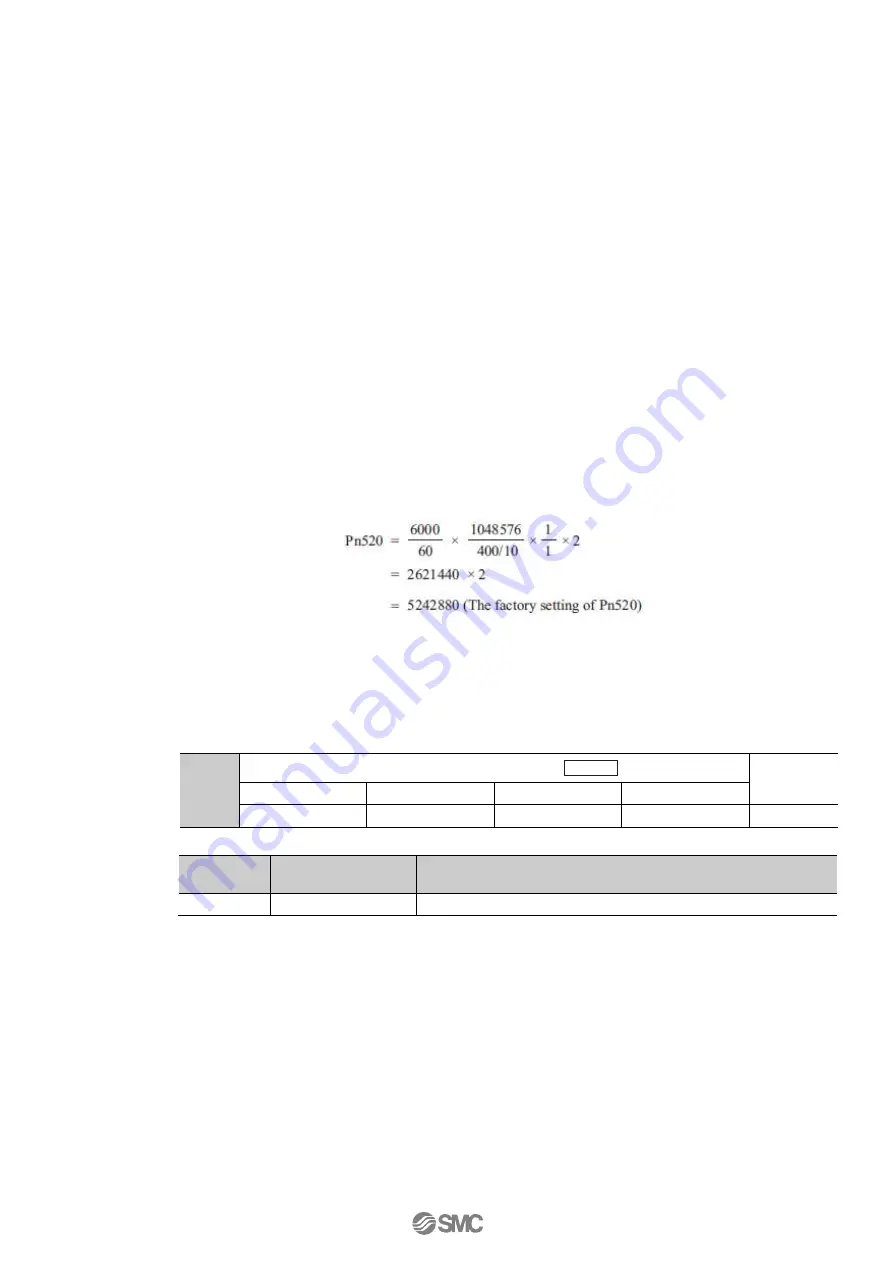
Under these conditions, the following equation is used to calculate the maximum limit
(Pn520).
If the acceleration/deceleration of the position reference exceeds the capacity of the
servomotor, the servomo- tor cannot perform at the requested speed, and the allowable level
for position error will be increased as not to satisfy these equations. If so, lower the level of
the acceleration/deceleration for the position reference so that the servomotor can perform at
the requested speed or increase the excessive position error alarm level (Pn520).
- Related Parameter
Pn520
Excessive Position Error Alarm Level
Position
Classification
Setting Range
Setting Unit
Factory Setting
When Enabled
1 to 1073741823
1 reference unit
5242880
Immediately
Setup
- Related Alarm
Alarm
Display
Alarm Name
Meaning
A.d00
Position Error Overflow
Position errors exceeded parameter Pn520.
(4) Vibration Detection Function
Set the vibration detection function to an appropriate value with the vibration detection level
initialization (Fn01B). For details on how to set the vibration detection function, refer to
6.15
Vibration Detection Level Initialization (Fn01B)
.
(5) Excessive Position Error Alarm Level at Servo ON
If position errors remain in the error counter when turning ON the servomotor power, the
servomotor will move and this movement will clear the counter of all position errors. Because
the servomotor will move suddenly and unexpectedly, safety precautions are required. To
prevent the servomotor from moving suddenly, select the appropriate level for the excessive
position error alarm level at servo ON (Pn526) to restrict opera- tion of the servomotor.
Summary of Contents for LECYU Series
Page 30: ...1 Outline 1 9 1 4 3 Three phase 200 V LECYU2 V9 Models ...
Page 65: ...3 Wiring and Connection 3 11 3 Wiring Example with DC Power Supply Input DRIVER ...
Page 92: ...3 Wiring and Connection 3 38 External Dimensions Units mm 1 FN Type by Schaffner EMC Inc ...
Page 93: ...3 Wiring and Connection 3 39 2 FN Type ...
Page 143: ...4 Operation 4 44 ...


