


3 Wiring and Connection
3-24
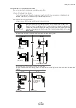
(2) Line Driver Output Circuit
CN1 connector terminals, 17-18 (phase-A signal), 19-20 (phase-B signal), and 21-22 (phase-Z signal) are explained
below.
These terminals output the following signals via the line-driver output circuits.
•
Output signals for which encoder serial data is converted as two phases pulses (PAO, /PAO, PBO, /PBO)
•
Origin pulse signals (PCO, /PCO)
Connect the line-driver output circuit through a line receiver circuit at the PC or PLC...etc.
Line Receiver Circuit Example
DRIVER
PC or PLC...etc
Applicable line receiver:
SN75ALS175 or the
equivalent
220 to
470
Ω
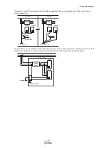
(3) Safety Output Circuit
The external device monitor (EDM1) for safety output signals is explained below.
A configuration example for the EDM1 output signal is shown in the following diagram.
Output signal is the source output. It is not able to use the sink output.
DRIVER
PC or PLC...etc
CN8
24 V Power Supply
8 EDM1+
7 EDM1-
0 V
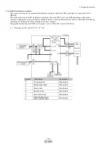
- Specifications
Type
Signal Name
Pin No.
Output
Status
Meaning
Output
EDM1
CN8-8
CN8-7
ON
Both the /HWBB1 and /HWBB2 signals are working nor-
mally.
OFF
The /HWBB1 signal, the /HWBB2 signal, or both are not
working normally.
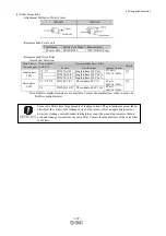
Electrical characteristics of EDM1 signal are as follows.
Items
Characteristic
Remarks
Maximum Allowable Voltage
30 VDC
−
Maximum Current
50 mADC
−
Maximum Voltage Drop at ON
1.0 V
Voltage between EDM1+ to EDM1- at current is 50 mA.
Maximum Delay Time
20 ms
Time from the change in /HWBB1 or /HWBB2 until the
change in EDM1.
Summary of Contents for LECYU Series
Page 30: ...1 Outline 1 9 1 4 3 Three phase 200 V LECYU2 V9 Models ...
Page 65: ...3 Wiring and Connection 3 11 3 Wiring Example with DC Power Supply Input DRIVER ...
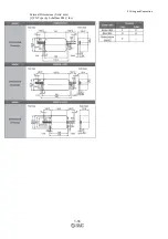
Page 92: ...3 Wiring and Connection 3 38 External Dimensions Units mm 1 FN Type by Schaffner EMC Inc ...
Page 93: ...3 Wiring and Connection 3 39 2 FN Type ...
Page 143: ...4 Operation 4 44 ...


