4 Operation
4-34
4.7.1 Connecting the Absolute Encoder
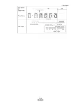
The following diagram shows the connection between a servomotor with an absolute encoder, the DRIVER,
and the host PC or PLC...etc.
(1) Using an Encoder Cable with a Battery Case
∗1.
The absolute encoder pin numbers for the connector wiring depend on the servomotors.
∗2.
: represents shielded twisted-pair wires.
∗3.
When using an absolute encoder, provide power by installing an encoder cable with a Battery Case.
DRIVER
PC or PLC ...etc
Z
Z
Summary of Contents for LECYU Series
Page 30: ...1 Outline 1 9 1 4 3 Three phase 200 V LECYU2 V9 Models ...
Page 65: ...3 Wiring and Connection 3 11 3 Wiring Example with DC Power Supply Input DRIVER ...
Page 92: ...3 Wiring and Connection 3 38 External Dimensions Units mm 1 FN Type by Schaffner EMC Inc ...
Page 93: ...3 Wiring and Connection 3 39 2 FN Type ...
Page 143: ...4 Operation 4 44 ...


