Hardware Preparation and Installation
ATCA-F140 Series Installation and Use (6806800M67S)
65
–
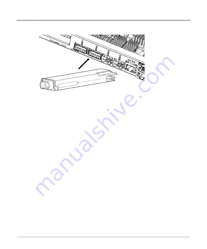
For QSFP+ transceivers with a pull-tab, make sure that the identifier label is on top.
–
Firmly press the front of the QSFP+ transceiver to push fully the transceiver in the
module’s transceiver socket. Make sure that it is fully engaged to prevent it from
being accidentally disconnected.
–
For optical QSFP+ modules, reinstall the dust plug into the portal. Do not remove
it until the network interface cable will be attached.
2.9.2
Removing QSFP+ Transceiver Modules
Removal Procedure
1.
For optical QSFP+ transceivers, disconnect the network interface cable from the
QSFP+ transceiver connector.
2.
Perform the following steps to remove QSFP+ transceivers with a bail-clasp latch:
–
Turn the bail-clasp down to the horizontal position.
–
Install the dust plug into the transceivers optical bore.
–
Hold the sides of the QSFP+ transceiver and slide it out of the module socket.
3.
Perform the following steps to remove QSFP+ transceivers with a pull tab latch:
–
Install the dust plug into the transceiver’ optical bore.
–
Hold the tab and pull the receiver gently to release the transceiver from the socket.
–
Slide the transceiver from the socket.
4.
Place the QSFP+ transceiver into an anti-static bag.


