56
ATCA-F140 Series Installation and Use (6806800M67S)
Hardware Preparation and Installation
Hardware Preparation and Installation
6. Wait until the blue LED is switched off, then tighten the face plate screws which secure
the blade to the shelf. When the blue LED is switched OFF and the green LED shows
IS (In Service) is switched ON, this indicates that the payload has been powered up
and that the blade is active.
7.
Connect cables to the face plate, if applicable.
2.6.2
Removing the Blade
This section describes how to remove the blade from an AdvancedTCA system.
The following procedure describes how to remove the blade from a system. It assumes that
the system is powered. If the system is powered down, you can disregard the blue LED and
skip the respective step. In that case it is a purely mechanical procedure.
Removal Procedure
1.
Unlatch the handle from the face plate by sliding the latch into the release position and
pull out the handle outward. Do not pull the handle fully outward. The blue LED blinks
indicating that the blade power-down process is ongoing.
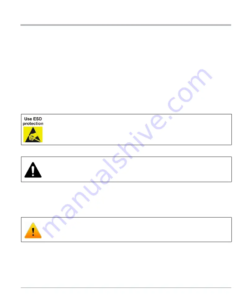
Electrostatic discharge and incorrect blade installation and removal can damage
circuits or shorten its life.
Before touching the blade or electronic components, make sure that you are working
in an ESD-safe environment.
Blade Damage
Incorrect installation of the blade can cause damage of the blade.
Only use handles when installing/removing the blade to avoid damage/deformation
to the face plate and/or PCB.
Data Loss
Removing the blade with the blue LED still blinking causes data loss.
Wait until the blue LED is steadily lit before removing the blade.


