


974-25007001/2.0
SL 30/35 Hull Sonar Operators Manual
Page 2.6
System Description
Kongsberg Simrad Mesotech Ltd.
Port Coquitlam, BC - Canada
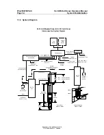
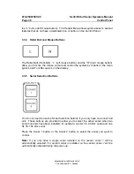
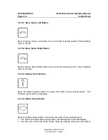
2.1.5.1 Transceiver Unit
The Transceiver Unit is mounted on the tank flange in a standard installation, but
can also be bulkhead mounted if required. The maximum Sonar Dome cable length
permissible is 5.1 meters depending on the shaft length used during the installation.
The Transceiver Unit contains the receiver and transmitter PCB assembly and the
lower and raise PCB assembly. A safety power ON/OFF switch is also provided so
power can be shut off when working on the lower and raise assembly. The
transceiver assembly is splash proof to protect the electronics circuits from water.
Note:
The safety power ON/OFF switch is not required for the SL 30 Sonar.
2.1.5.2 Lower and Raise Unit
The SL 35 Lower and Raise Unit is a self-contained hydraulic assembly. Installation
is simple and only requires the fitting of 2 clevis pins and connection of the power
cable from the Transceiver Unit.
.
The travel length is available in two sizes, 250 millimeters and 400 millimeters
depending on the installation requirement.
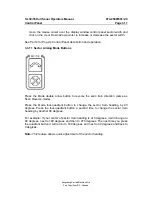
2.1.5.3 Hull Sonar Dome Unit
The Hull Sonar Dome unit is available in two frequencies, 90kHz and 160 kHz. The
cable length is available in 4.5 meters for a 2.4 or 3 meter shaft and 5.1 meters with
a 3.6 meters optional shaft. Special attention must be paid to matching cable and
shaft lengths when ordering the system.
Note:
The SL 30 Catch Sonar Dome comes with a standard 5 meter cable length.
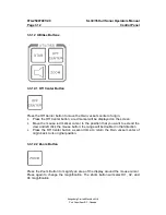
2.1.5.4 Tank Flange Assembly
The SL 35 Tank Flange Assembly main body is cast in ASTM A536, 60-40-18
Ductile Iron. Special mounting pads and a guide are incorporated into the flange.
The shaft bearing is made of SEA 660 Bearing Bronze. Special attention was given
during the design to the seal and shaft packing in order to prevent water leakage
into the sonar room. A zinc anode is also installed on the tank flange, to reduce
electrolysis.
Note:
The Tank Flange Assembly is not required for the SL 30 Dome; all flanges are
serial-numbered.
Summary of Contents for SL 30
Page 1: ...SL 30 35 HULL SONAR OPERATORS MANUAL 974 25007001 Issue 2 0 September 2003...
Page 2: ......
Page 207: ......
Page 208: ......
Page 209: ......
Page 210: ......
Page 211: ......
Page 212: ......
Page 213: ......
Page 214: ......
Page 215: ......
Page 216: ......
Page 217: ......
Page 218: ......
Page 219: ......
Page 220: ......
Page 221: ......
Page 222: ......
Page 223: ......
Page 224: ......


