SL 30/35 Hull Sonar Operators Manual
974-25007001/2.0
Selecting Settings
Page 5.17
Kongsberg Simrad Mesotech Ltd.
Port Coquitlam, BC - Canada
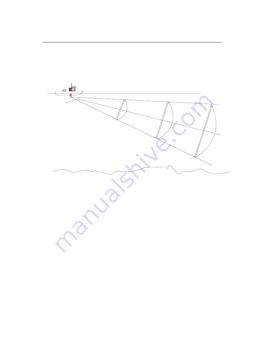
5.5.2 Tilt Angle and Beam Coverage
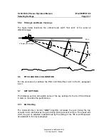
The figure below illustrates the vertical beam width “foot print” of the sonar at
different ranges
8 Degrees Beam Angle
100 m
200 m
300 m
14 m
26 m
44 m
5.6
PITCH AND ROLL CALIBRATION
For the procedure to calibrate the Pitch and Roll offset, refer to Part 6, paragraph
6.6.11
5.7 KEY
SETTINGS
The following section will explain some of the key settings for the SL 35 Hull Sonar
in order to maximize the performance.
5.7.1 AGC
Setting
The Automatic Gain Control “
AGC”
algorithm increases
the gain during the low
acoustic return and reduces the gain during strong acoustic returns. The speed with
which the gain is adjusted is determined by the setting of the “RX Gain Response”
as explained in the next paragraph.
Summary of Contents for SL 30
Page 1: ...SL 30 35 HULL SONAR OPERATORS MANUAL 974 25007001 Issue 2 0 September 2003...
Page 2: ......
Page 207: ......
Page 208: ......
Page 209: ......
Page 210: ......
Page 211: ......
Page 212: ......
Page 213: ......
Page 214: ......
Page 215: ......
Page 216: ......
Page 217: ......
Page 218: ......
Page 219: ......
Page 220: ......
Page 221: ......
Page 222: ......
Page 223: ......
Page 224: ......

