


Gantry axes (G1)
6.3 Referencing and synchronizing gantry axes
Turning, Milling, Nibbling
98
Function Manual, 11/2012, 6FC5397-1CP10-5BA0
Absolute encoder
During the synchronization compensatory motion, all the axes in the gantry axis grouping (in
the decoupled state) also traverse to the reference point value of the leading axis, which is
defined in the following machine data:
MD34100 REFP_SET_POS (reference point value/destination point for distance-coded
system)
The absolute encoders and distance-coded encoders of the leading axis will be set to the
current actual position of the leading axis or to the reference point value; either of these
options is set using the following machine data:
MD34330 REFP_STOP_AT_ABS_MARKER
(distance-coded linear measuring system without destination point)
Activation of axis compensations
Compensation functions can be activated for both the leading axis and the synchronized
axis. Compensation values are applied separately for each individual gantry axis. These
values must therefore be defined and entered for the leading axis and the synchronized axes
during start-up.
The compensations do not become operative internally in the control until the axis is
referenced or the gantry grouping synchronized. The following applies:
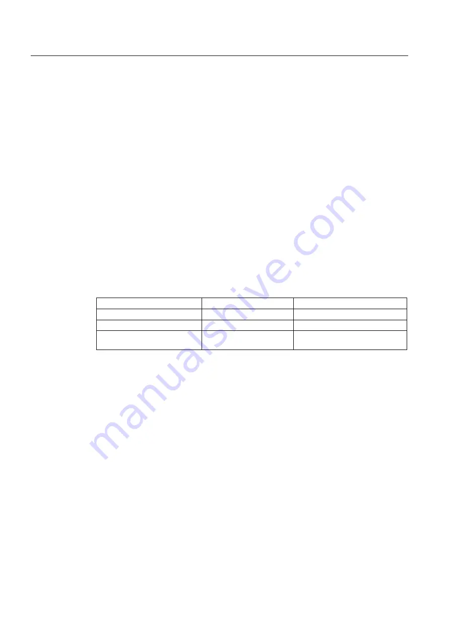
Compensation type
Takes effect when
PLC interface signal
Backlash compensation
Axis is referenced
"Referenced/Synchronized"
LEC
Axis is referenced
"Referenced/synchronized"
Sag compensation
Gantry grouping is
synchronized
"Gantry grouping is synchronized"
If active compensation causes the synchronized axis to move, a traverse command is
displayed for the synchronized axis, independently of the leading axis.
Monitoring functions effective
Analogous to normal NC axes, the following monitoring functions do not take effect for gantry
axes until the reference point is reached (IS "Referenced/Synchronized"):
●
Working area limits
●
Software limit switch
●
Protection zones
The axial machine data values are used as monitoring limit values for the synchronized axis
as well.