


Kinematic Transformation (M1)
12.3 TRACYL
Turning, Milling, Nibbling
Function Manual, 11/2012, 6FC5397-1CP10-5BA0
241
Required assignment of channel axes for TRACYL transformation in machine data
MD24110:
Configuration without YM axis:
TRAFO_AXES_IN_1[0]=
Channel axis number of axis radial to rotary axis
TRAFO_AXES_IN_1[1]=
Channel axis number of rotary axis
TRAFO_AXES_IN_1[2]=
Channel axis number of axis parallel to rotary axis
Configuration without existing YM axis:
TRAFO_AXES_IN_1[3]
Channel axis number of axis parallel to peripheral cylinder surface
and perpendicular to rotary axis (→ YM axis)
Machine data specifically for TRACYL
●
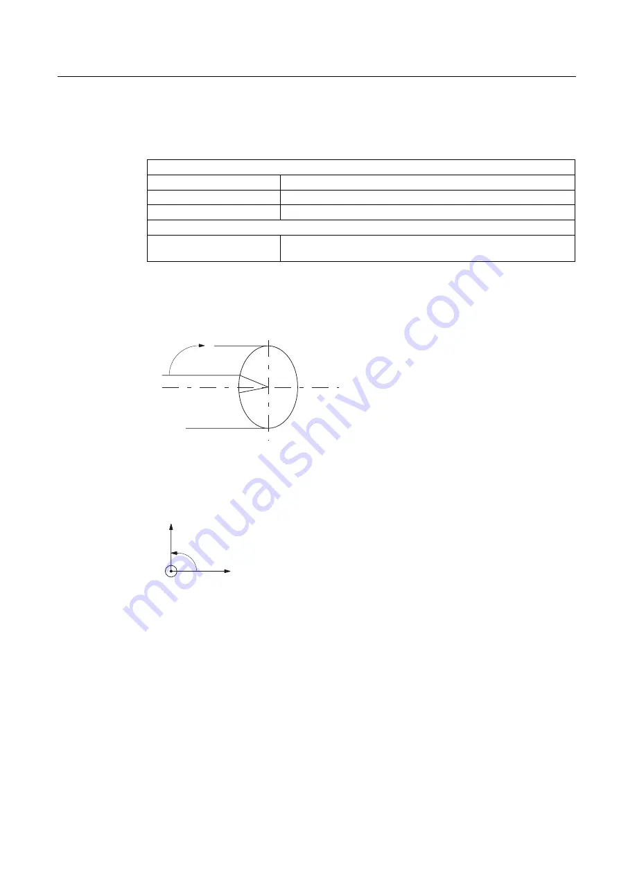
MD24900 TRACYL_ROT_AX_OFFSET_1
Rotational position: rotary axis setting, when Y=0 (in degrees 0... < 360)
$QJOHDELQGHJUHHV
D5RWDWLRQDOSRVLWLRQRIURWDU\D[LV
ZLWK&
E3RVLWLRQRI<
E
D
<
Figure 12-8 Rotational position of axis in the peripheral cylinder surface
●
MD24910 TRACYL_ROT_SIGN_IS_PLUS_1
If the rotary axis rotates in an anti-clockwise direction on the X-Y plane opposite to the
positive Z axis, then the MD must be set to 1, otherwise to 0.
\
[
Figure 12-9 Direction of rotation for MD value =1
●
MD24920 TRACYL_BASE_TOOL_1
The control is informed of the position of the tool zero point in relation to the origin of the
coordinate system declared for TRACYL. The MD has three components for the three
axes of the Cartesian coordinate system.