


Gantry axes (G1)
6.7 Example
Turning, Milling, Nibbling
110
Function Manual, 11/2012, 6FC5397-1CP10-5BA0
In addition, the following steps must be taken:
●
RESET
●
Read off values in machine coordinate system:
e.g.
X = 0.941
Y = 0.000
XF = 0.000
●
Enter the X value of the leading axis (axis 1) with inverted sign in the machine data of the
synchronized axis (axis 3):
MD34090 REFP_MOVE_DIST_CORR = - 0.941
Note
This MD is effective after POWER ON. To avoid having to perform a POWER ON in
advance, this value can also be entered in the following machine data:
MD34080 REFP_MOVE_DIST (reference point distance)
The MD is then valid after a RESET.
●
Start referencing again for axis 1 with the modified machine data
●
Wait until message "10654 Channel 1 Waiting for synchronization start" appears
●
At this point, the NCK has prepared axis 1 for synchronization and sends the same
interface signal as shown in the image above:
●
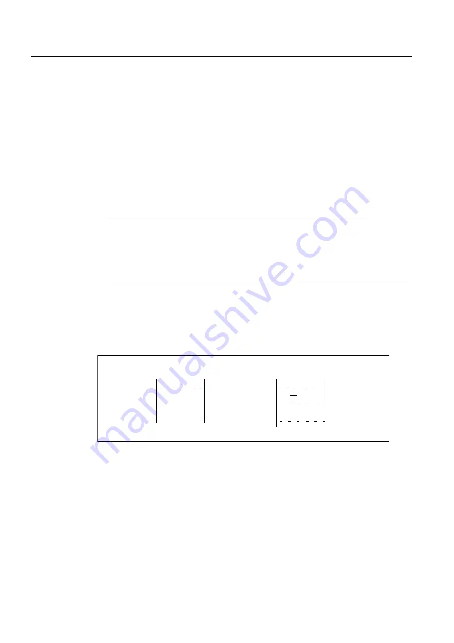
Examine actual positions of machine. Case A or B might apply:
!5
5!
GLII
&DVH%
!
$
$
&DVH$
!
$
$
Figure 6-8
Possible results of referencing the leading axis
If Case A applies, the synchronization process can be started immediately. See step "Start
synchronization". If Case B applies, the offset "diff" must be calculated and taken into
account:
●
Measuring of diff
●
By using two appropriate, right-angled reference points R and R" in the machine bed (at
the right of the image), the difference in position can be traversed in JOG. The diff offset
can then be read as the difference in the position display. The diff offset must be entered
in the machine data of axis 3 (synchronized axis):
MD34100 REFP_SET_POS