


Operating Modes, Program Operation (K1)
10.3 Processing a part program
Turning, Milling, Nibbling
Function Manual, 11/2012, 6FC5397-1CP10-5BA0
187
The start signal must be set to logical 0 by the user once the ASUB has been completed or if
an error has occurred.
Note
The call of the ASUB PI service must have been completed before an ASUB may be started.
Initialization
The initialization is performed via the ASUB PI service, see also Section "Starting PI services
in the NCK area (A2)".
Starting an ASUB
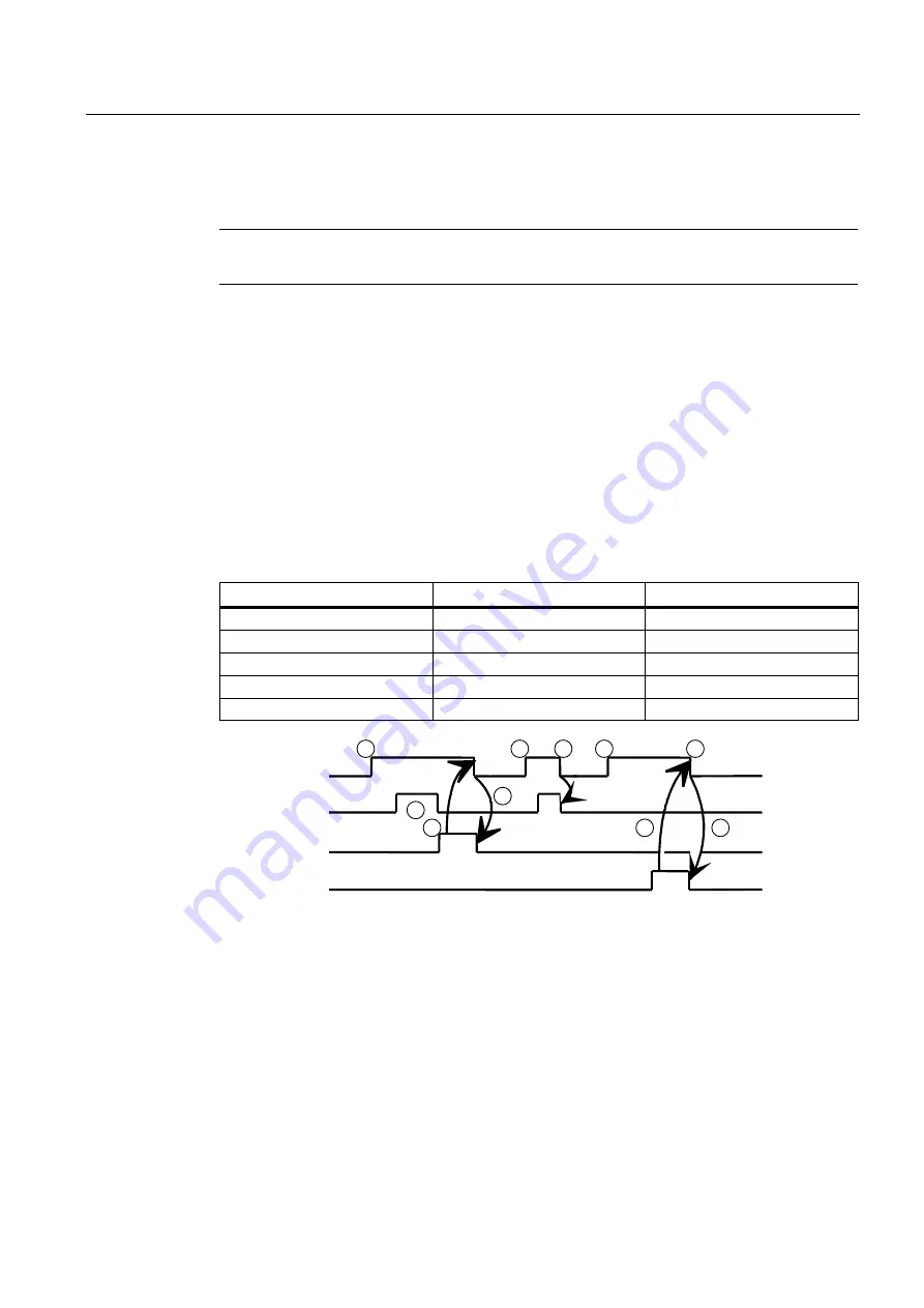
The time sequence of an ASUB is shown in the following pulse diagram in the example of
PLCASUP1_SPF. You can see from the table which interface signals are of relevance for
PLCASUP2_SPF.
Table 10- 11 Assignment of the signals to the pulse diagram
Signal
Address - PLCASUP1_SPF
Address - PLCASUP2_SPF
Start
V3400 0000.0
V3400 0001.0
Being executed
V3400 1000.1
V3400 1001.1
Completed
V3400 1000.0
V3400 1001.0
Error
V3400 1000.3
V3400 1001.3
Interrupt no. not allocated
V3400 1000.2
V3400 1001.2
6WDUW
%HLQJH[HFXWHG
&RPSOHWHG
(UURU
9
9
9
9
①
Function activation via positive edge of Start
②
ASUB is being executed
③
Positive acknowledgment: ASUB ended
④
Reset function activation after receipt of acknowledgment
⑤
Signal change through PLC
⑥
not permitted. If function activation is reset prior to receipt of acknowledgment, the output
signals are not updated without the operational sequence of the activated function being
affected
⑦
Negative acknowledgment: Error has occurred
Figure 10-3 Pulse diagram for PLCASUP1_SPF