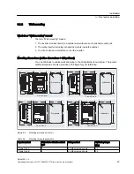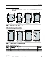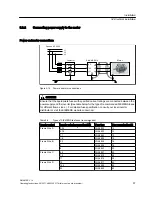
Drill patterns and cut-out dimensions
Please drill holes and cut out an opening in cabinet wall according to the data specified in the
figure below:
)UDPH6L]H$
)UDPH6L]H%
)UDPH6L]H&
)UDPH6L]H'
154
142
156.8
7.4
6
2
2
7
8
0
9
0
1
7
0
2
8
.5
2-
8
4-
6
&XWRXWDUHD
152
164
2
5
7
8
0
1
7
0
4
3
.5
9
0
&XWRXWDUHD
6
2-
8
4-
6
&XWRXWDUHD
166.8
7.4
8- 6
220
7.9
235.8
3
2
7
9
0
9
0
9
9
.4
2
3
.8
&XWRXWDUHD
242.3
11.1
1
3
5
.2
1
4
5
.2
2- 8
262
8
278
3
9
2
5
1
1
1
0
1
5
0
1
1
0
7
0
&XWRXWDUHD
278.7
8.3
1
4
0
2
- 8
8- 6
Figure 5-7
Drill pattern and cut-out dimensions (in mm)
Outline dimensions of optional mounting kits
)UDPH6L]H$VSHFLILF
)UDPH6L]H%VSHFLILF
)UDPH6L]H&VSHFLILF
)UDPH6L]H'VSHFLILF
257.6
3
6
1
8- 5
.8
2
- 4
.1
4- 1
0
294
4
4
5
172
2
6
2
4- 5
.8
182
2
9
2
4- 5
.8
4- 5
.8
Figure 5-8
Outline dimensions of optional mounting kits (in mm)
Table 5-3
Mounting torque requirements
Inverter
variant
Holes to be drilled
in cabinet wall
Fixing method
Tightening
torque (Nm)
Frame Size A 6
4 x M5 screws and nuts; 2 x plastic rivets
2.5
Frame Size B 6
4 x M5 screws and nuts; 2 x plastic rivets
2.5
Frame Size C 10
8 x M5 screws and nuts; 2 x plastic rivets
2.5
Installation
5.1 Mechanical installation
SINAMICS V10
Operating Instructions, 08/2011, A5E03453178 (this is not an order number)
27

