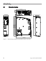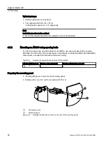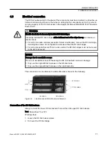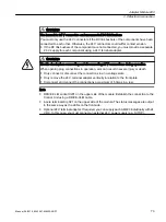
3. Fasten the DC link screws with a tightening torque of 1.8 Nm (15.9 lbf in). It is essential that
you follow the sequence shown below (1 and 2).
4. Tighten the DC link screw on the right-hand side of the module for the components of the
drive line-up arranged on the far right with a tightening torque of 1.8 Nm (15.9 lbf in).
The power connection of the DC link busbar with the module is established via the right-
hand screw mounting (3).
1. Connection of the lower DC link busbars
2. Connection of the upper DC link busbars
Connection of the 24 V busbars
The 24 V busbars of the components are connected using the 24 V connectors in the
accessories pack. A 24 V connector must be plugged onto the 24 V busbars between the Line
Module, Motor Module and DC link component. The 24 V connectors must be attached before
the drive line-up is commissioned.
Working steps:
1. Place the 24 V connectors on to the 24 V busbars.
2. Press the 24 V connectors down until they click into place.
3. If required, mount the 24 V terminal adapter to supply the 24 VDC.
①
Mounted 24 V terminal adapter (Torx T10, tightening torque 0.5 Nm (4.4 lbf in))
②
Mounted 24 V connector
Adapter Module 600
4.8 Electrical connection
72
Manual, 06/2019, 6SL3097-5AW00-0BP1
Summary of Contents for Sinamics S120M
Page 2: ......
Page 20: ...Introduction 1 8 General Data Protection Regulation 18 Manual 06 2019 6SL3097 5AW00 0BP1 ...
Page 56: ...System overview 3 5 System Data 54 Manual 06 2019 6SL3097 5AW00 0BP1 ...
Page 110: ...S120M 5 11 Motor holding brake 108 Manual 06 2019 6SL3097 5AW00 0BP1 ...
Page 118: ...DRIVE CLiQ Extension 6 6 Technical data 116 Manual 06 2019 6SL3097 5AW00 0BP1 ...
Page 126: ...Hybrid Cabinet Bushing 7 6 Technical data 124 Manual 06 2019 6SL3097 5AW00 0BP1 ...
Page 182: ...Appendix A 2 Documentation overview 180 Manual 06 2019 6SL3097 5AW00 0BP1 ...
Page 185: ......


