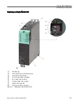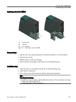
Replacing an Adapter Module 600
①
Mounting lugs
②
X21 terminal strip for the operating state
③
X201 DRIVE-CLiQ interface
④
24 V terminal adapter, if available
⑤
24 V busbar (cover opened)
⑥
DC link busbars (cover opened)
⑦
Hybrid cable connection
Protective conductor connection
Figure 9-1
Replacing an Adapter Module 600
Service and maintenance
9.2 Replacing components
Manual, 06/2019, 6SL3097-5AW00-0BP1
157
Summary of Contents for Sinamics S120M
Page 2: ......
Page 20: ...Introduction 1 8 General Data Protection Regulation 18 Manual 06 2019 6SL3097 5AW00 0BP1 ...
Page 56: ...System overview 3 5 System Data 54 Manual 06 2019 6SL3097 5AW00 0BP1 ...
Page 110: ...S120M 5 11 Motor holding brake 108 Manual 06 2019 6SL3097 5AW00 0BP1 ...
Page 118: ...DRIVE CLiQ Extension 6 6 Technical data 116 Manual 06 2019 6SL3097 5AW00 0BP1 ...
Page 126: ...Hybrid Cabinet Bushing 7 6 Technical data 124 Manual 06 2019 6SL3097 5AW00 0BP1 ...
Page 182: ...Appendix A 2 Documentation overview 180 Manual 06 2019 6SL3097 5AW00 0BP1 ...
Page 185: ......


