


2-5
Installation
NOTE: When you select non-supervision
for an annunciator, there must also be one
and only one supervised annunciator at
the same address. The supervisory mode
is independent of the network address.
To set for supervision
S1-SW5 = Closed (ON)
To set for non-supervision
S1-SW5 = Open (OFF)
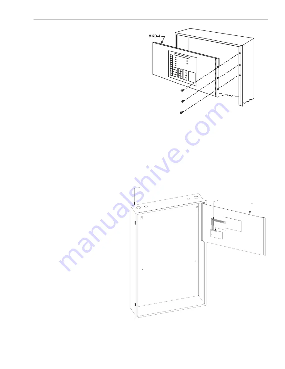
Mounting the MKB-4
(Refer to Figure 26)
1. Install three screws in the first group of
three tapped holes in the right flange.
Leave a
1
/
8
-inch gap between the head
of the screw and the flange. Slide the
slots of the MKB-4 panel hinge under the
head of the screws and tighten.
2. After the MKB-4 is mounted to the
enclosure, connect the cable (P/N 555-
192238) between P1 on the ANN-1 (on
the back of the MKB-4) and P8 on the
SMB-2.
CAUTION:
Be sure the black tracer wire on the edge of
the cable is close to the 1 on position 1 of
connector P1 on the ANN-1 and the 1 on
position 1 of P8 on the SMB-2.
7. Install the PIM-1, PIM-2, and PAL-1
PIM-1
1. Install the PIM-1 on the back of the
MKB-4 panel as shown in Figure 27.
Position the PIM-1 so the TB1 is on the
left side of the board.
2. Mount the PIM-1 module on the raised
studs with the hardware provided.
3. Using the cable supplied with the PIM-1,
connect PIM-1, P-1 to ANN-1, P1 (See
Figure 27).
4. Using the cable supplied with the MKB-4,
connect PIM-1, P2 to SMB-2, P8 (See
Figure 27).
Figure 26
Installing the MKB-4 Keyboard/Annunciator
MSE-3L
Back of MKB-4
P2
P1
TB1
P1
1
ANN-1
PIM-1
To P8 on
the SMB-2
(Cable
supplied
with MKB-4)
Cable supplied
with PIM-1
(P/N 555-192242)
Figure 27
Installing a PIM-1 on the Back of an MKB-4
Summary of Contents for MXL-IQ
Page 50: ...2 20 Installation ...
Page 126: ...A 2 Appendix A ...
Page 128: ...B 2 Appendix B ...
Page 138: ...F 4 Appendix F ...
Page 140: ...G 2 Appendix G ...
Page 142: ...H 2 Appendix H ...
Page 154: ...K 2 Appendix K ...
Page 162: ...L 8 Appendix L ...
Page 166: ...M 4 Appendix M ...
Page 168: ...N 2 Appendix N ...
Page 178: ...Index 6 Index ...


