


Installation
Completing the Installation
42
Building Technologies
125-202
06/06/2017
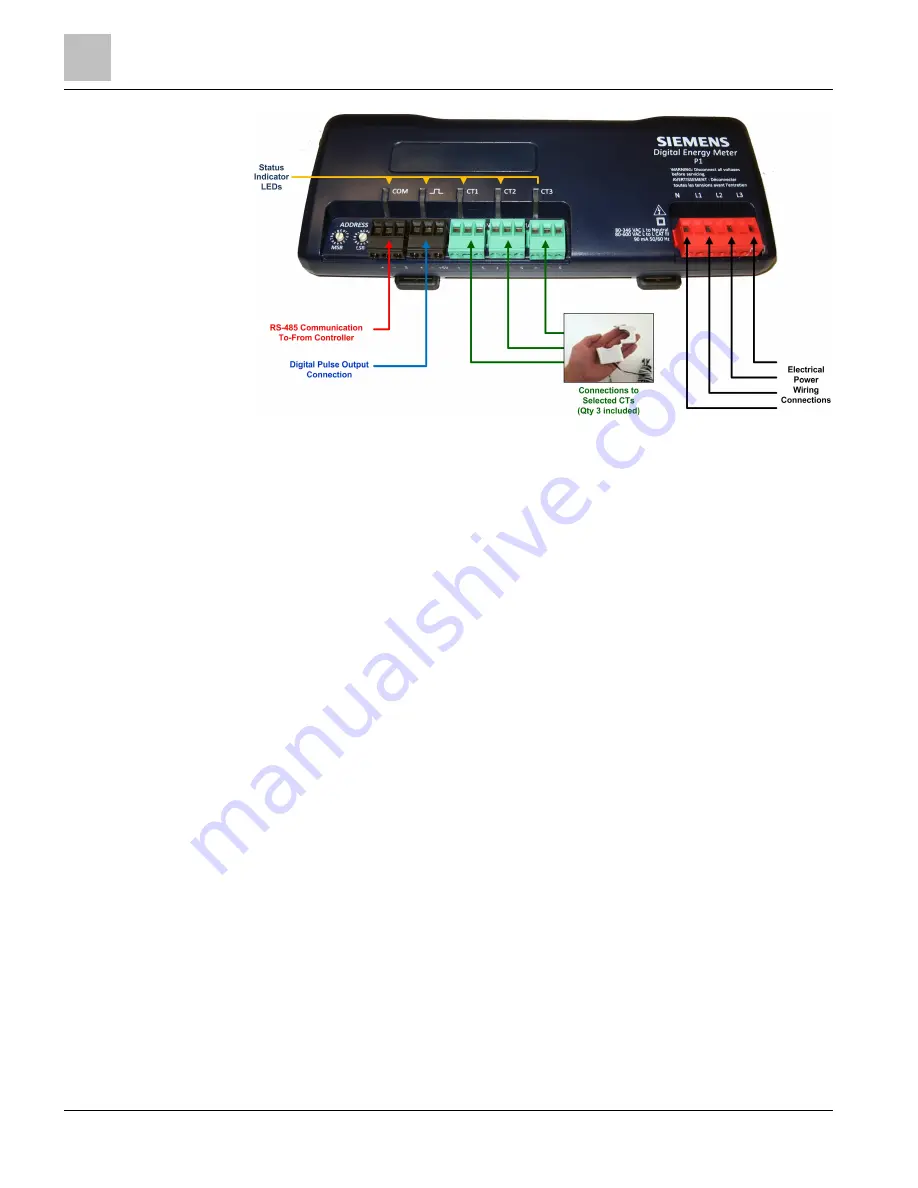
Figure 6: Power Meter Connections.
Completing the Installation
Follow these steps to complete the field installation of your MD-BM or MD-BMED
Power Meter:
●
Connect whatever communications cable you are using to the building network.
Recommendation: Use Belden® DataTuff® TC Cat 5e cord sets with UL 1277 Listed,
Type TC 600V Industrial Ethernet Cable. See
Belden Product Bulletin PB372.
1. Connect your pulse output, if used. The port can be used to output kWh, kVARh, or
kVAh pulses to external devices, or to toggle on and off to control a remote device
or relay. See
Using the Pulse Output Port Function.
2. Connect the CTs. See
Wiring CTs.
3. Connect the voltage and power the meter. See
Connecting Voltage.
Using the Digital Pulse Output Port Function
The Digital Pulse Output (see Figure 5) is used to generate pulses for external devices
such as data loggers that can accept pulses, but do not have BACnet or Modbus
capability. The MD-BMS or MD-BMED can generate pulses based on accumulated
value(s) such as system kWh, system kVARh, and system kVAh. When a pulse is
generated by the meter, the pulse LED will briefly flash; otherwise, it will remain dark.
When in Modbus, the pulse output is scaled by the Modbus data scalar register 44602.
When in BACnet, the pulse output is scaled by the CT Pulse Scalar object 12030. The
pulse scalar table is the same as the Modbus data scalar table. For example, when the
data scalar is set to 3, each pulse will represent .1kWh, .1kVAh and .1kVARh.