


Prepping for Installation
Connecting the Ports
36
Building Technologies
125-202
06/06/2017
Enter a new value into any field and click Send Setup to Meter to update the Device ID
(meter identification), Max Master (number of units on network), or Max Info Frames
(Number of packets sent using MS/TP).
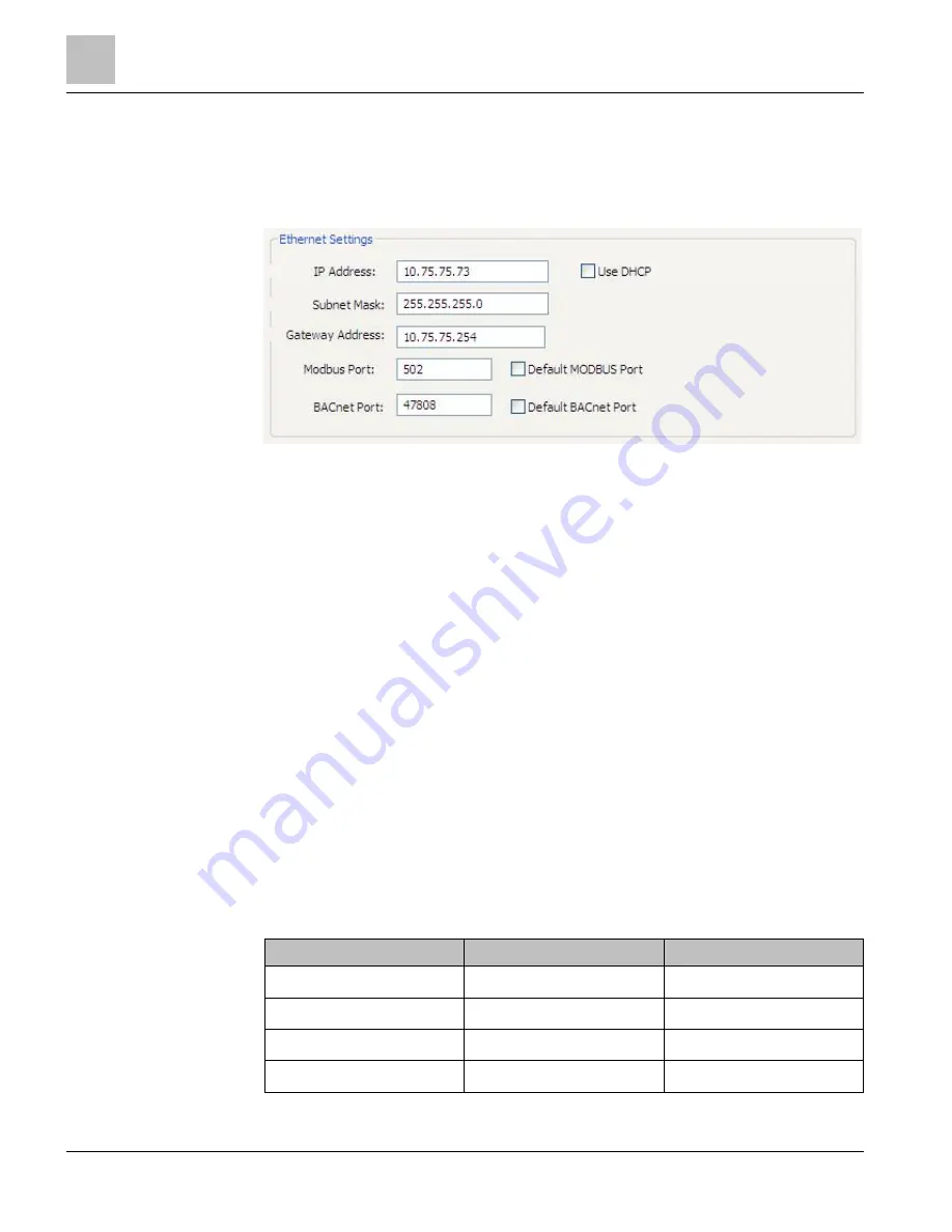
Ethernet Settings
Connecting the Ports
Once your communication mode is selected, click Connect to establish a connection
between the computer and the MD-BMS or MD-BMED meter.
●
When the MD-BMS or MD-BMED meter is in the process of connecting to the
computer, the Communication Status LED flashes briefly, followed by a solid
green.
●
If the MD-BMS or MD-BMED meter cannot connect to the computer, the
Communication Status LED flashes red, and then returns to a solid green. Change
the ViewPoint hardware settings and click Connect again.
ViewPoint fills the Device Info fields when the computer communicates with the meter.
MD-BMS and MD-BMED meter installation can be verified using the ViewPoint
software. See
Using ViewPoint Software further in this document for more information.
Establishing Communication Protocol
The MD-BMS and MD-BMED Power Meters communicate using the BACnet MS/TP or
Modbus RTU protocols through the RS 485/Ethernet interface. To establish
communication with a RS-485, the settings must meet the following requirements:
●
The Modbus/BACnet address on the MD meter and in the ViewPoint software must
be set to the same value.
●
The MD-BMS and MD-BMED meter default serial parameters are:
Table 9: Serial Communication Settings.
Parameter Defaults
Modbus Settings
BACnet Settings
Baud (default)
9600
76800
Data bits
8
8
Parity
None
None
Stop Bit
1
1