


33
8011952/YWL2/3-0/2016-08| SICK
O P E R A T I N G I N S T R U C T I O N S | DUSTHUNTER C200
Subject to change without notice
ASSEMBLY AND INSTALLATION
3
3
Assembly and Installation
3.1
Project planning
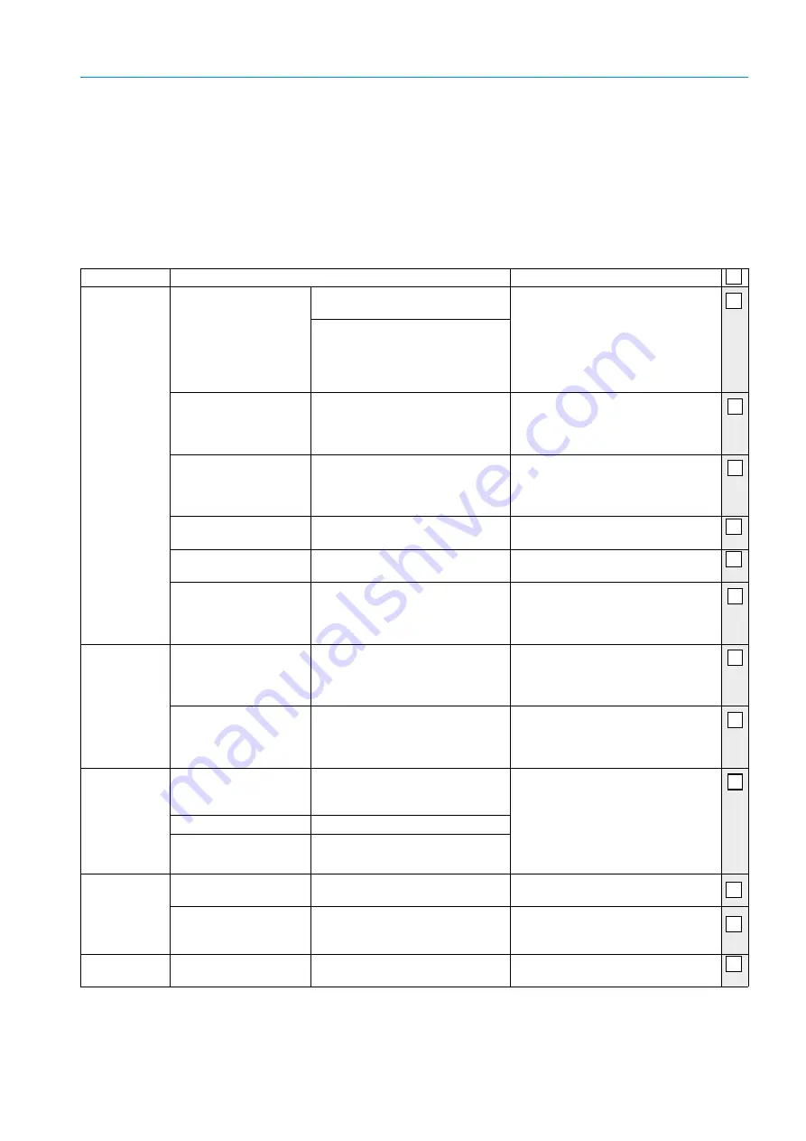
The following Table provides an overview of the project planning work necessary as prereq-
uisite for trouble-free assembly and subsequent device functionality. You can use this Table
as a Checklist and check off the completed steps.
Task
Requirements
Work step
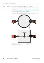
Determine the
measuring and
installation loca-
tions for the
device compo-
nents
Inlet and outlet paths
according to DIN EN
13284-1 (inlet at least 5x
hydraulic diameter d
h,
out-
let at least 3x d
h
; distance
to stack opening at least
5x d
h
)
For round and square ducts:
d
h
= duct diameter
●
Follow specifications for new equip-
ment
●
Select best possible location for exist-
ing equipment;
●
For too short inlet/outlet paths:
Inlet path > outlet path
For rectangular ducts:
d
h
= 4x cross-section divided by cir-
cumference
Homogeneous flow distri-
bution
Representative dust distri-
bution
Whenever possible, no deflections,
cross-section variations, feed and
drain lines, flaps or fittings in the area
of the inlet and outlet paths
If conditions cannot be ensured, define
flow profile according to DIN EN 13284-
1 and select best possible location
Assembly position for
sender/receiver unit and
reflector/scattered light
receiver
Do not fit vertically on horizontal or
slanted ducts;
max. measuring axis angle to horizon-
tal 45
°
Select best possible location
Accessibility, accident pre-
vention
The device components must be eas-
ily and safely accessible
Provide platforms or pedestals as
required
Installation free of vibra-
tions
Acceleration < 1 g
Eliminate/reduce vibrations through
suitable measures
Ambient conditions
Limit values according to Technical
Data
If necessary:
●
Provide weatherproof covers/sun
protection
●
Enclose or lag device components
Select the purge
air supply
Sufficient primary purge
air pressure depending on
internal duct pressure
Up to +2 hPa, MCU control unit with
integrated purge air supply
Above +2 hPa to +30 hPa, optional
external purge air unit
Select supply type
Clean intake air
Whenever possible, low amount of
dust, no oil, moisture or corrosive
gases
●
Select best possible location for air
intake
●
Determine required purge air hose
length
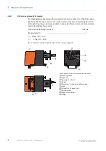
Select device
components
Active measuring path,
duct wall thickness with
isolation
Sender/receiver unit, reflector/scat-
tered light receiver, flange with tube
●
Select components according to the
Configuration Table (
)
;
●
If necessary, plan additional mea-
sures to fit the flange with tube (
“Fitting the flange with tube”,
page 35
Internal duct pressure
Type of purge air supply
Fitting locations
Line and purge air hose lengths
Plan calibration
openings
Access
Easy and safe
Provide platforms or pedestals as
required
Distances to measuring
level
No mutual interference between
calibration probe and measuring sys-
tem
Plan sufficient distance between
measuring and calibration level (approx.
500 mm)
Plan the voltage
supply
Operating voltage, power
requirements
According to Technical Data (
Plan adequate line cross-sections and
fuses


