63
8011952/YWL2/3-0/2016-08| SICK
O P E R A T I N G I N S T R U C T I O N S | DUSTHUNTER C200
Subject to change without notice
START-UP AND PARAMETER SETTINGS
4
4.2.3
Scaling the measuring system for transmission measurement
▸
Process successively the steps shown in field “Transmission set reference” in directory
“Adjustment / Manual adjustment / Transmission set reference” (
DH C200/Adjustment/Manual Adjustment/Transmission set reference”, page 60
).
While the steps are processed, the associated indicator lights yellow.
▸
Check whether the value 100% is displayed in window “Transmission reference value”
(
see “SOPAS ET menu: DH C200/Adjustment/Manual Adjustment/Transmission set ref-
) after this process is completed. When the deviations (< approx. 1%)
are small, click the “Set reference” button, when the deviations are large, repeat setting
of reference.
4.2.4
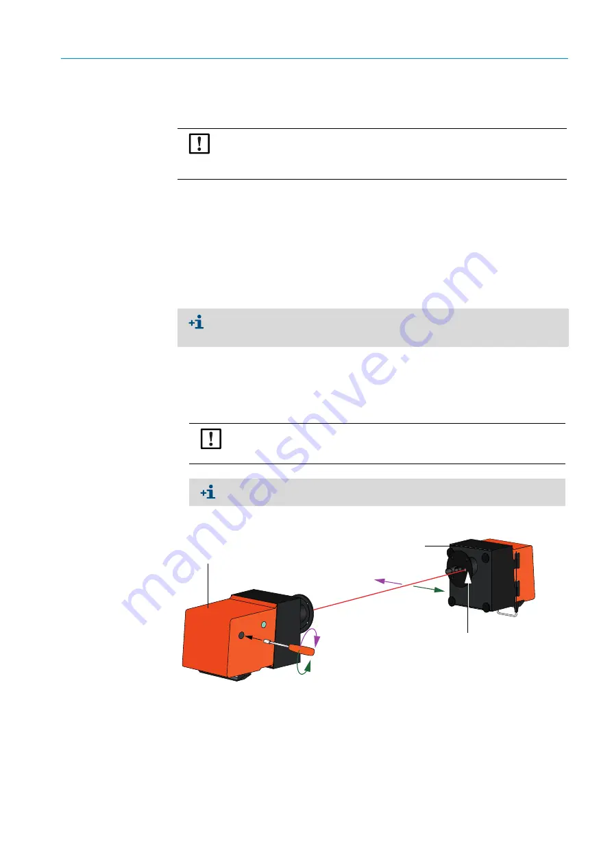
Adjusting the laser beam for scattered light measurement
▸
Take off the sender/receiver unit cover and use an SW 7 socket wrench to set the
adjusting nut so that the laser beam disappears in the light trap on the reflector/
scattered light receiver.
Fig. 40: Aligning the laser beam to the light trap
▸
Put the cover back on.
NOTE:
The optical surfaces must be clean (clean if necessary before performing the following
steps;
see “Maintenance on the sender/receiver unit and reflector/scattered light
The values shown in field “Set reference result” in window “Sender/receiver unit refer-
ence value” and “Reflector reference value” must not exceed 8% (otherwise there could
be a device defect
→
contact SICK Customer Service).
NOTE:
Do not change the alignment of sender/receiver unit and reflector/scattered light
receiver.
The sender/receiver unit and the reflector/scattered light receiver must be
connected via the connection line, otherwise no laser beam is visible.
X
Y
Y
X
Reflector/scattered light
receiver
Light trap
Sender/receiver unit


