18
8011952/YWL2/3-0/2016-08| SICK
O P E R A T I N G I N S T R U C T I O N S | DUSTHUNTER C200
Subject to change without notice
2
PRODUCT DESCRIPTION
2.2.1
Sender/receiver unit
The sender/receiver unit contains the optical and electronic subassemblies to send and
receive the reflected light beam of the transmission measurement as well as to process
and evaluate the signals. Swivel mechanisms are also fitted for contamination
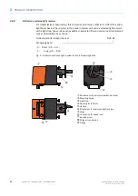
measurement and self-alignment (
see “Pivoted shutter settings on the sender/receiver
and
see “Self-alignment principle design”, page 19
).
Data transfer to and power supply (24 V DC) from the MCU control unit run via a shielded
line with 4 wires and plug connector. Clean air to cool the device and keep the optical
surfaces clean is fed via a purge air connection.
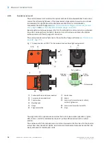
The sender/receiver unit is fastened to the duct with a flange with tube (
).
Fig. 7: Sender/receiver unit DHC-T for transmission and scattered light measurement
The alignment of the optical axes as well as the current device state (operation = green
LED, failure = red LED, maintenance request = yellow LED) are shown at the control
window.
The enclosure with fitted sender/receiver unit can be swiveled to the side after the knurled
screws have been loosened. Optics, electronics and mechanical components can then be
easily accessed for maintenance work.
A
A
B
B
à
Enclosure with electronics (swivel-mounted)
Knurled screw
Cover screw for laser adjustment
Handle
Control window
Connection for connection line to reflector/
scattered light receiver
Mounting holes
Flange
Connection of connection line to MCU
Purge air connection
à
Hinge
Control window
Status
indicator
Alignment
indicator
Distance scale


