78
8011952/YWL2/3-0/2016-08| SICK
O P E R A T I N G I N S T R U C T I O N S | DUSTHUNTER C200
Subject to change without notice
4
START-UP AND PARAMETER SETTINGS
4.4.7.2
Calibrating dust concentration measurement based on scattered light measurement
▸
Select device file “MCU”, set the measuring system to “Maintenance” mode
▸
Enter the Level 1 password (
see “Password and operating levels”, page 84
▸
Select the “Configuration / IO Configuration / Output Parameters DUSTHUNTER”
directory (
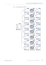
see “SOPAS ET menu: MCU/Configuration/IO configuration/Output Param-
) and assign the “SI” (scattered light intensity) measured variable to an
analog output.
▸
Estimate the measuring range required for the dust concentration in operational state
and enter this in the “Analog Output 1
(2/3)
Scaling” field assigned to the selected
analog output assigned to the scattered light intensity.
▸
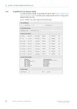
Select the “Configuration / Application Parameter” directory
C200/Configuration/Application parameter (example)”, page 64
) and then select
“Scattered light” in the “Primary measuring principle” field.
▸
Deactivate “Maintenance” mode.
▸
Carry out the gravimetric comparison measurement according to DIN EN 13284-1.
▸
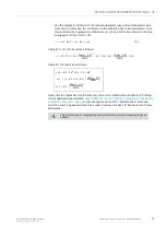
Determine regression coefficients from the mA values of the analog output for
“Scattered light intensity” and the actual dust concentrations measured gravimetrically.
c:
Dust concentration in mg/m³
K2, K1, K0:
Regression coefficients of the function c = f (I
out
)
I
out
:
Current output value in mA
SI:
Measured scattered light intensity
LZ:
Live Zero
MBE:
Defined upper range limit value
(value entered for 20 mA;
normally 2.5 x fixed limit value)
c
K2 I
out
2
⋅
K1 I
out
⋅
K0
+
+
=
(1)
I
out
LZ SL
20mA LZ
–
MBE
-----------------------------
⋅
+
=
(2)


