


80
Manual – MOVIDRIVE® MDX60B/61B Communication and Fieldbus Unit Profile
7
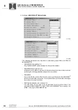
Process data description
SEW Unit Profile
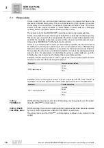
Assignment
Meaning
Scaling
NO FUNCTION
The setting
NO FUNCTION
has the effect that the drive inverter
does not use this process output data word for processing set-
points. The content of the process output data word programmed
to
NO FUNCTION
is ignored although the controller might specifiy
a real setpoint via the fieldbus system.
The NO FUNCTION setting just disables the processing of the
process output data word in the inverter system. However, you
can access the process output data at any time using IPOS
plus®
.
SPEED
Set to
SPEED
, the
MOVIDRIVE
®
inverter interprets the setpoint
value transmitted by this process data word to be the speed set-
point if the selected operating mode (
P700 operating mode 1
,
P701 operating mode 2) allows a speed setpoint.
If no speed setpoint has been programmed although a communi-
cation interface (FIELDBUS, RS485, system bus) has been set as
setpoint source, the inverter will use speed setpoint = 0.
1 digit = 0.2/min
CURRENT
Set to
CURRENT
, the drive inverter will interpret the setpoint
specified in this process data word as current setpoint if a variant
with torque control is set as operating mode (
P700 Operating
mode 1
). Else, the drive inverter ignores the current setpoint.
1 digit = 0.1 % I
N
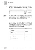
POSITION LO / HI
When set to
POSITION HI / POSITION LO
, the drive inverter
passes the setpoint received via these process output data (usu-
ally a position setpoint) as 32-bit value directly to the IPOS
plus®
program in IPOS
plus®
variable
499 SP.PO.BUS (setpoint position
bus)
.
The position setpoints must be split into two process data words
because the position is usually specified as signed 32-bit value.
This means you have to specify the higher-value position value
(POSITION HI)
as well as the lower-value position setpoint
(POSITION LO)
. Else, the drive inverter will not accept these
process output data in the IPOS
plus®
program.
MAX. SPEED
Set to
MAX. SPEED
means the MOVIDRIVE
®
inverter interprets
the transmitted setpoint as speed limit. The speed limit is speci-
fied in rpm and is interpreted as value for both directions of rota-
tion.
The supported value range of the speed limit via fieldbus corre-
sponds to the value range of parameter
P302 Maximum speed 1
.
Specifying the speed limit via fieldbus automatically disables
parameters
P302 Maximum speed 1, P312 maximum speed 2
.
1 digit = 0.2/min
MAX. CURRENT
Set to
MAX. CURRENT
means the MOVIDRIVE
®
inverter inter-
prets the transmitted process output data as current limit. The
current limit is specified in percent with reference to the rated
inverter current, in the unit % I
N
and is interpreted as value for
both directions of rotation.
The supported value range of the current limit via fieldbus corre-
sponds to the value range of parameter
P303 Current limit 1
. The
current limits that can be set using parameters
P303 Current limit
1
and
P313 Current limit 2
are still valid when the current limit is
specific using process data. This means these parameters are to
be regarded as maximum effective current limit.
1 digit = 0.1 % I
N
Summary of Contents for MOVIDRIVE MDX60B
Page 2: ...SEW EURODRIVE Driving the world...
Page 142: ......
Page 143: ...SEW EURODRIVE Driving the world...


