


Manual – MOVIDRIVE® MDX60B/61B Communication and Fieldbus Unit Profile
77
7
Process data
SEW Unit Profile
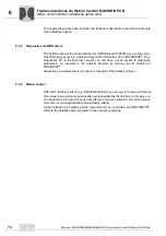
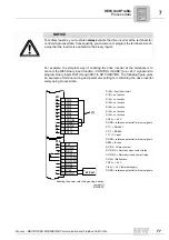
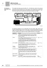
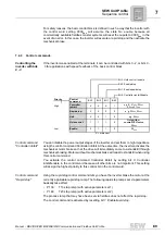
For example, the simplest way of enabling the drive inverter at the terminals is to
connect the DI00 binary input (function /
CONTROL INHIBIT
) to a +24 V signal and to
program binary inputs DI01 through DI07 to
NO FUNCTION
. The following figure gives
an example of terminal wiring and parameter setting for controlling the drive inverter
solely using process data.
NOTICE
For safety reasons, you must also
always
enable the drive inverter at the terminals for
control via process data. Consequently, you must wire or program the terminals in such
a way that the inverter is enabled via the binary inputs.
DI00 = /Controller inhibit
DI01 = no function
DI02 = no function
DI03 = no function
DI04 = no function
DI04 = no function
DI05 = no function
VO24 = + 24 V
DGND = reference potential for binary signals
ST11 = RS-485 +
ST12 = RS-485 -
TF1 = TF input
DGND = reference potential for binary signals
DB00 = /Brake
DO01-C = Relay contact
DO01-NO = Normally open contact relay
DO01-NC = Normally closed contact relay
DO02 = /Malfunction
VO24 = + 24 V
VI24 = + 24 V (external supply)
DGND = reference potential for binary signals
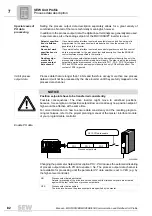
Enabling the power output stage using a device
jumper [1]
01234BXX
+
-
X13:
DI00
DI01
DI02
DI03
DI04
DI05
DCOM
VO24
DGND
ST11
ST12
24 V ext.
-
-
-
TF1
DGND
DB00
DO01-C
DO01-NO
DO01-NC
DO02
VO24
VI24
DGND
X10:
[1]
1
2
3
4
5
6
7
8
9
10
11
1
2
3
4
5
6
7
8
9
10
Summary of Contents for MOVIDRIVE MDX60B
Page 2: ...SEW EURODRIVE Driving the world...
Page 142: ......
Page 143: ...SEW EURODRIVE Driving the world...


