38
Manual – MOVIDRIVE® MDX60B/61B Communication and Fieldbus Unit Profile
5
Configuration parameters of the CAN interfaces
CAN Interfaces of MOVIDRIVE® B
5.2
Configuration parameters of the CAN interfaces
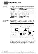
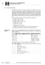
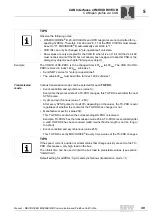
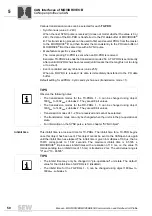
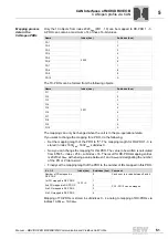
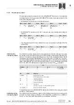
Set the following parameters to enable communication via CAN interfaces:
Parameter
No. Name
Setting
Meaning
100
Setpoint source
SBus 1/2
The inverter obtains its setpoint from the SBus.
101
Control signal source
SBus 1/2
The inverter receives its control commands
from the SBus.
836
837
Response to SBus timeout
1/2
Factory set to:
EMERG.STOP/FAULT
The error response is programmed that is
triggered by system bus timeout monitoring.
870
871
872
Setpoint description PO1
Setpoint description PO2
Setpoint description PO3
Factory set to:
CONTROL WORD 1
SPEED
NO FUNCTION
The content of process input data words
PO1/PO2/PO3 is defined. This is necessary so
MOVIDRIVE
®
can allocate the appropriate
setpoints.
873
874
875
876
Actual value description PI1
Actual value description PI2
Actual value description PI3
Enable PO data
Factory set to:
STATUS WORD 1
SPEED
NO FUNCTION
ON
The content of process input data words
PI1/PI2/PI3 is defined. This is necessary so
MOVIDRIVE
®
07 can allocate the appropriate
actual values. The process data must be
enabled to have the unit apply the setpoints.
881
882
SBus address 1/2
0 - 63
Setting of the SBus address used for
exchanging parameter and process data.
882
892
SBus group address 1/2
0 - 63
Setting for the SBus group address used for
receiving group parameter and group process
data.
883
893
SBus timeout interval 1/2
0 - 650 s
Monitoring time for data transmission via SBus.
MOVIDRIVE
®
performs the fault response set
in P836 if there is no data traffic on the SBus
within this time. Data transmitted via SBus is
not monitored when P815 is set to 0 or 650 s.
884
894
SBus baud rate 1/2
125/250/500/1000
kBaud
The transmission speed of the SBus is set.
885
895
SBus synchronization ID 1/2 0 - 2047
P817 is used for setting the identifier (address)
of the synchronization message in the inverter
for the SBus. Make sure there is no overlap
between the identifiers for the process data or
parameter data telegrams.
887
External controller synchroni-
zation
On/off
By default, the time base of MOVIDRIVE
®
units
is slightly smaller than 1 ms. For synchroniza-
tion with an external controller, the time base
can be set to exactly 1 ms.
888
Synchronization time
1 - 5 - 10 ms
This parameter is used to specify the time inter-
val for synchronous data transfer
(see P885/P895).
889/
899
Parameter channel 2
Yes / No
Parameter channel 2 is only needed with the
MOVI-PLC
®
option. In this case, master/slave
operation via SBus is not possible.
TIP
Refer to the MOVIDRIVE
®
MDX60B/61B system manual for a detailed description of
the parameters.
Summary of Contents for MOVIDRIVE MDX60B
Page 2: ...SEW EURODRIVE Driving the world...
Page 142: ......
Page 143: ...SEW EURODRIVE Driving the world...

