


Manual – MOVIDRIVE® MDX60B/61B Communication and Fieldbus Unit Profile
17
4
Configuration parameters of the serial interfaces
Serial Interfaces of MOVIDRIVE® B
4.2
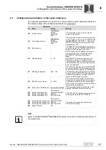
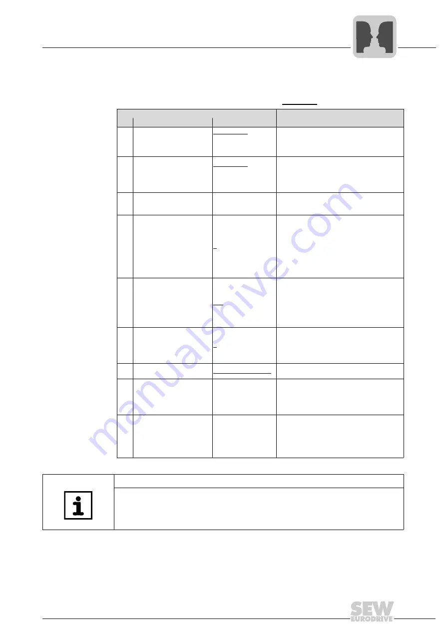
Configuration parameters of the serial interfaces
The following parameters are used to set communication via the
two
serial interfaces.
The factory setting of the individual parameters is underlined.
Parameter
No. Name
Setting
Meaning
100
Setpoint source
TERMINALS
RS485
FIELDBUS
SBus
This parameter is used to set the setpoint
source for the inverter.
101
Control signal source
TERMINALS
RS485
FIELDBUS
SBus
This parameter is used to set the source of the
control signals for the inverter (CONTROLLER
INHIBIT, ENABLE, CW, CCW, ...). Control via
IPOS
plus®
and terminal is taken into account
disregarding of P101.
750
Slave setpoint
The setpoint to be transferred to the master is
set on the master. The "MASTER-SLAVE OFF"
setting must be retained on the slave.
810
RS485 Address
0 ... 99
P810 is used to set the address by means of
which communication can take place with
MOVIDRIVE
®
via the serial interfaces.
Note:
MOVIDRIVE
®
B units are always set to the
address 0 on delivery. To avoid problems
during data exchange in serial communication
with several inverters, we recommend that you
do not use address 0.
811
RS485 group address
100 ... 199
P811 allows for grouping several MOVIDRIVE
®
B units in one group for communication via the
serial interface. For example, the RS485 group
address allows for sending setpoint selections
to a group of MOVIDRIVE
®
B inverters simulta-
neously. Group address 100 means that the
inverter is not assigned to a group.
812
RS485 Timeout interval
0 ... 650 s
P811 sets the monitoring time for data trans-
mission via the serial interface. No monitoring
of serial data transmission takes place when
P812 is set to 0. Monitoring is activated with the
first cyclical data exchange.
833
Response to RS485 timeout RAPID STOP/WARN.
P833 programs the fault response that is trig-
gered by the RS485 timeout monitoring.
870
871
872
Setpoint description PO1
Setpoint description PO2
Setpoint description PO3
Factory set to:
CONTROL WORD 1
SPEED
NO FUNCTION
P870/P871/P872 define the content of the pro-
cess output data words PO1/PO2/PO3.
873
874
875
876
Actual value description PI1
Actual value description PI2
Actual value description PI3
Enable PO data
Factory set to:
STATUS WORD 1
SPEED
NO FUNCTION
ON
The content of process input data words
PI1/PI2/PI3 is defined.
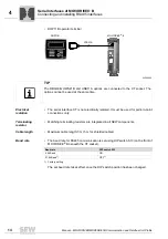
TIP
Refer to the MOVIDRIVE
®
MDX60B/61B system manual for a detailed description of
the parameters.
Summary of Contents for MOVIDRIVE MDX60B
Page 2: ...SEW EURODRIVE Driving the world...
Page 142: ......
Page 143: ...SEW EURODRIVE Driving the world...


