


Manual – MOVIDRIVE® MDX60B/61B Communication and Fieldbus Unit Profile
37
5
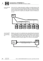
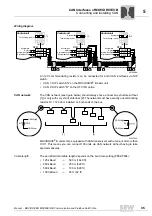
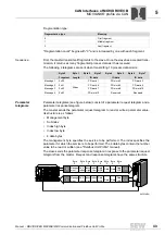
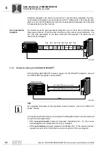
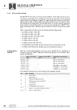
Connecting and installing CAN
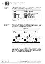
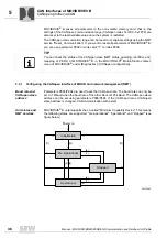
CAN Interfaces of MOVIDRIVE® B
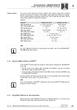
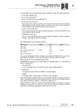
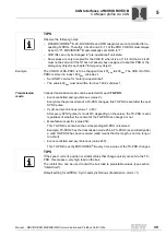
CAN cable
specification
• Use a 2 x 2-core twisted and shielded copper cable (data transmission cable with
braided copper shield). The cable must meet the following specifications:
– Cable cross section 0.25 - 0.75 mm
2
(AWG 23 - AWG 19)
– Cable resistance 120
Ω
at 1 MHz
– Capacitance per unit length
≤
40 pF/m at 1 kHz
Suitable cables are e.g. CAN bus or DeviceNet cables.
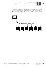
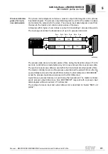
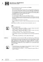
Shield contact
• Connect the shield on both sides to the electronics shield clamp of MOVIDRIVE
®
B
over a large area. With a 2-core cable, additionally connect the shield ends to GND.
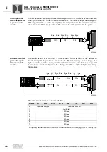
NOTICE
There must not be any difference of potential between the units which are connected
using CAN 1 (Sbus 1). This may affect the functionality of the units.
Take suitable measures to avoid potential displacement, such as connecting the unit
ground connectors using a separate cable.
Summary of Contents for MOVIDRIVE MDX60B
Page 2: ...SEW EURODRIVE Driving the world...
Page 142: ......
Page 143: ...SEW EURODRIVE Driving the world...


