


4
76
System Manual – MOVITRAC® 07
Explanation of the parameters
Parameters
62_
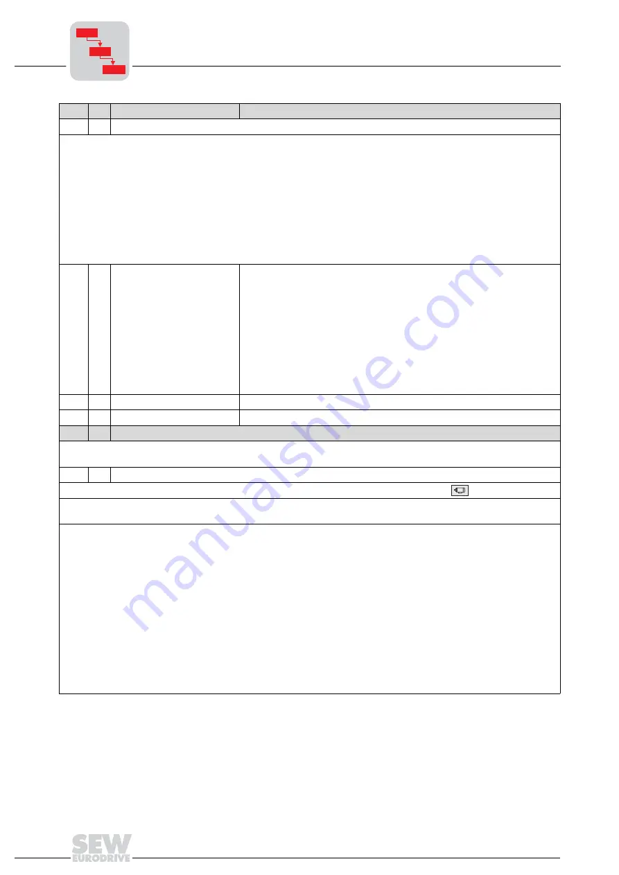
Binary outputs
Effect of
0 signal
1 signal
NO FUNCTION: -
-
/FAULT:
Collective fault signal
-
READY: Not ready
Ready
OUTP. STAGE ON:
Unit inhibited
Unit enabled and motor is energized
ROT. FIELD ON:
No rotating field Rotating field
BRAKE RELEASED:
Brake is applied
Brake is released
SPEED REFERENCE: n > n
ref
/ n < n
ref
(P403) n < n
ref
/ n > n
ref
(P403)
SP/ACT.VAL.COMP.: n
≠
n
set
n = n
set
PI ACT.VALUE REF.:
-
Actual value has exceeded the set threshold during PI control
IPOS OUTPUT:
Depends on LOGODrive program
/IPOS FAULT:
Fault indicator in LOGODrive
62-
•
Binary outputs
DO01
DO02
0
/FAULT
BRAKE RELEASED
1
READY
BRAKE RELEASED
2
SPEED REFERENCE
BRAKE RELEASED
3
SP/ACT.VAL.COMP.
BRAKE RELEASED
4
/FAULT
SPEED REFERENCE
5
/FAULT
SP/ACT.VAL.COMP.
6
/FAULT
READY
7
/FAULT
ROT. FIELD ON
8
/FAULT
PI ACT.VALUE REF
9
PI ACT.VALUE REF
BRAKE RELEASED
-
(Deviating combination set with MOVITOOLS)
620
Binary output DO01
Factory setting: /FAULT
621
Binary output DO02
Factory setting: BRAKE RELEASED
7__
Control functions
All settings with regard to the fundamental control properties of the inverter are defined within parameter group 7__. The
parameter group includes functions which the inverter performs automatically when activated.
70_
Operating modes
This parameter sets the basic operating mode of the inverter. Set on the operating panel with
, P-01.
VFC / V/f character.: Default setting for asynchronous motors. Suited to general applications such as conveyor belts,
trolleys and hoists with a counterweight.
VFC & HOIST (only in units with expanded functions or LOGODrive units): The hoist function automatically provides all
functions required for operating a non-balanced hoist. In particular, monitoring functions are activated for safety reasons.
These may prevent the drive from starting. Monitoring functions are:
•
Monitoring the output current during the pre-magnetization phase
•
Avoiding sag when the brake is released
•
Monitoring that the pre-magnetization time is set to an adequate value
The unit detects the following incorrect configurations and displays them with the following faults:
•
2 or 3-phase motor phase interruption: F82 = Output open
•
Premagnetization time too short, or incorrect motor/inverter combination: F81 = Fault start condition
•
Failure of a motor phase by active speed monitoring P500/501: F08 = Fault n-monitoring
Important!
•
A single-phase motor phase failure cannot always be reliably detected.
•
SEW-EURODRIVE strongly recommends that you activate speed monitoring.
•
Precondition for correct procedure in the hoisting function: Motor brake controlled by the inverter.
•
Do not set the minimum speed P301 less than the slip compensation P324.
No.
OP Name
Description
P6..
P60.
P600


