8-Rock Noggin Configuration Assembly (Noggin 500 & 1000 only)
Noggin
40
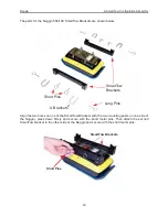
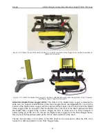
Figure: 8-8 Using the 4 holes on the bottom of the Rock Noggin frame, place the frame on the 4 mounting posts on
the top of the Noggin (shown in Figure 8-6). Push the frame down until it cannot go any further. The Noggin should be
oriented such that the 37 socket receptacle on the Noggin is on the same side as the SmartButton on the frame.
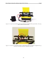
Figure: 8-9 Secure the frame to the Noggin by pushing the 4 metal pins into the holes on the frame as shown.
Metal Pins
Summary of Contents for Noggin 100
Page 1: ...User s Guide Copyright 2012 Sensors Software Inc 2011 00022 02 Noggin ...
Page 2: ......
Page 4: ......
Page 8: ......
Page 17: ...Noggin 2 Noggin Components 3 Figure 2 3 Noggin 100 components ...
Page 156: ...Appendix D Instrument Interference Noggin D 2 ...
Page 158: ...Appendix E Safety Around Explosive Devices Noggin E 2 ...
Page 162: ...Noggin G 4 ...


