5-SmartCart Configuration Assembly
Noggin
14
5.5 Attaching the Noggin to the SmartCart
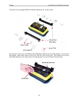
The Noggin is attached to the cart with the long axis of the Noggin unit parallel to the wheels on
the cart (see
Figure 5-9
and
Figure 5-10
). Ensure the 37 socket female electrical receptacle on
the Noggin faces the back of the cart so that the cable on the cart will reach the receptacle.
5.5.1
Noggin 250
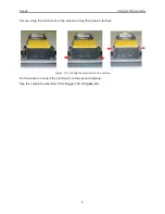
Remove the Clevis pins from the swivel adapters. Now, on the bottom of the cart, locate the 4
oval, moveable hangers suspended from the frame of the cart (see
Figure 5-9
). Notice that each
hanger has a hole in it. To attach the Noggin 250 to the cart, place each hanger into the slot on
the top of the swivel adapters, line up the holes and insert the Clevis pin.
Figure: 5-9 Attaching the Noggin 250 to the SmartCart.
Hanger
Clevis Pin
Swivel Adapter
Summary of Contents for Noggin 100
Page 1: ...User s Guide Copyright 2012 Sensors Software Inc 2011 00022 02 Noggin ...
Page 2: ......
Page 4: ......
Page 8: ......
Page 17: ...Noggin 2 Noggin Components 3 Figure 2 3 Noggin 100 components ...
Page 156: ...Appendix D Instrument Interference Noggin D 2 ...
Page 158: ...Appendix E Safety Around Explosive Devices Noggin E 2 ...
Page 162: ...Noggin G 4 ...

