


3-Noggin 100 Assembly
Noggin
4
3
Noggin 100 Assembly
Unlike the higher frequency Noggins (250, 500 and 1000 MHz), the Noggin 100 comes with the
antennas and electronics as separate units that need to be assembled.
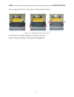
To assemble, space the 100 MHz antennas about 0.5 meters apart with the mounting blocks
facing up.
Figure: 3-1 Noggin 100 assembly of electronics to antenna.
Place one end of the Noggin 100 electronics module over one of the antennas and press
downward until it is seated.
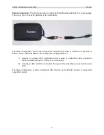
Figure: 3-2 Connecting the electronics to the 100 MHz antenna. The 2 brass sockets in the bottom of the electronics
mate with the 2 brass pins in the antenna mounting block.
System
Electronics
Antenna
Summary of Contents for Noggin 100
Page 1: ...User s Guide Copyright 2012 Sensors Software Inc 2011 00022 02 Noggin ...
Page 2: ......
Page 4: ......
Page 8: ......
Page 17: ...Noggin 2 Noggin Components 3 Figure 2 3 Noggin 100 components ...
Page 156: ...Appendix D Instrument Interference Noggin D 2 ...
Page 158: ...Appendix E Safety Around Explosive Devices Noggin E 2 ...
Page 162: ...Noggin G 4 ...