


4-Base Configuration Assembly
Noggin
6
4
Base Configuration Assembly
The Base Noggin Configuration consists of the parts shown in
Figure 4-1
(a Noggin 500 is
shown but any Noggin (100, 250, 500 or 1000) could be included). The assembled system is
shown in
Figure 4-2
. Follow the directions below to assemble the configuration.
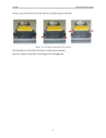
Figure: 4-1 Base Noggin 500 system components.
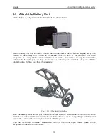
Figure: 4-2 Base Noggin system assembled.
Noggin
DVL
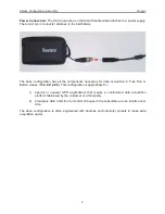
Belt Battery
Battery
Connection
DVL Connection
Cable
Noggin Connection
Summary of Contents for Noggin 100
Page 1: ...User s Guide Copyright 2012 Sensors Software Inc 2011 00022 02 Noggin ...
Page 2: ......
Page 4: ......
Page 8: ......
Page 17: ...Noggin 2 Noggin Components 3 Figure 2 3 Noggin 100 components ...
Page 156: ...Appendix D Instrument Interference Noggin D 2 ...
Page 158: ...Appendix E Safety Around Explosive Devices Noggin E 2 ...
Page 162: ...Noggin G 4 ...