6-SmartTow Configuration Assembly
Noggin
22
Assemble the Noggin 100 electronics and antennas as shown in
3: p.4
.
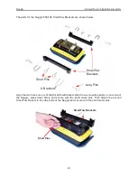
The parts for the Noggin 100 SmartTow frame are shown in
Figure 6-3
. Note that the SmartTow
frame is also used as part of the SmartCart separation bars. The assembly kit comes with extra
end pieces so both configurations can be assembled. The SmartTow requires the 4 corner
brackets shown below while the SmartCart separation bars requires 2 frame ends.
Do not be
alarmed when you have extra pieces after assembly!
Figure: 6-3 The Noggin 100 SmartTow frame parts (left) and assembled (right). Ensure the antenna post blocks face
outward before assembling. The pieces are connected using the 4 thumb screws as shown in the figure below. The
Handle and Big Wheel odometer are not connected to the frame with thumb screws but held in place once the 100
MHz antennas are attached.
Handle
Corner
Bracket
Antenna
Post Blocks
Thumb
Screw
Big Wheel
Odometer
Tow
Frame
Sides
Summary of Contents for Noggin 100
Page 1: ...User s Guide Copyright 2012 Sensors Software Inc 2011 00022 02 Noggin ...
Page 2: ......
Page 4: ......
Page 8: ......
Page 17: ...Noggin 2 Noggin Components 3 Figure 2 3 Noggin 100 components ...
Page 156: ...Appendix D Instrument Interference Noggin D 2 ...
Page 158: ...Appendix E Safety Around Explosive Devices Noggin E 2 ...
Page 162: ...Noggin G 4 ...


