


Noggin
6-SmartTow Configuration Assembly
27
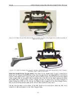
The yellow cable from the odometer connects to the receptacle on the connector to the Noggin.
Odometer calibration is critical for accurate data images. Odometer calibration instructions are
available in
13.5.2: p.120
.
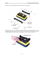
Attach the handle to the front SmartTow Bracket Assembly with the U-brackets and pins. The
black cable should lie between the SmartTow Bracket and the handle. Secure the cable along the
side of the handle using 2 or 3 Velcro straps.
Summary of Contents for Noggin 100
Page 1: ...User s Guide Copyright 2012 Sensors Software Inc 2011 00022 02 Noggin ...
Page 2: ......
Page 4: ......
Page 8: ......
Page 17: ...Noggin 2 Noggin Components 3 Figure 2 3 Noggin 100 components ...
Page 156: ...Appendix D Instrument Interference Noggin D 2 ...
Page 158: ...Appendix E Safety Around Explosive Devices Noggin E 2 ...
Page 162: ...Noggin G 4 ...