


8-Rock Noggin Configuration Assembly (Noggin 500 & 1000 only)
Noggin
38
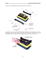
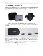
Figure: 8-4 The Rock Noggin system disassembled into its basic components and ready for assembly. More details
of each component are given in the figures below.
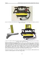
Figure: 8-5 The Rock Noggin cable. The 4 connections are for the Noggin, the Digital Video Logger (DVL), the trigger
button and the battery.
Summary of Contents for Noggin 100
Page 1: ...User s Guide Copyright 2012 Sensors Software Inc 2011 00022 02 Noggin ...
Page 2: ......
Page 4: ......
Page 8: ......
Page 17: ...Noggin 2 Noggin Components 3 Figure 2 3 Noggin 100 components ...
Page 156: ...Appendix D Instrument Interference Noggin D 2 ...
Page 158: ...Appendix E Safety Around Explosive Devices Noggin E 2 ...
Page 162: ...Noggin G 4 ...