DOCS-010 Manual, SeaBotix Inc. Users, 200 Series – 18 Mar 09 - Rev B - Page 43 of 52
There are three main areas of discussion with regards to troubleshooting the LBV:
Power Transmission, Communications Transmission and Video Transmission.
The LBV system works as follows:
Input power is rectified inside the Surface Power Supply, becoming 360 VDC for
transmission via the tether to the LBV. At the LBV, the 360 VDC is converted to 28 VDC
inside the Vehicle Power Supply (VPS).
There, two distinct 28 VDC bus lines have been created. One 28 VDC supply (Motherboard
power) runs directly to the Motherboard where it is used to service the internal electronics.
The other (backplane power) services the thrusters, grabber, external lighting and other
auxiliary equipment. The latter 28 VDC supply is monitored by an over current protection
circuit, which (in the event of a short in any of the external equipment) will remove supply
voltage from all external equipment. This feature prevents damage to the entire LBV system.
The high DC voltage from the surface allows for relatively low current on the tether, greatly
reducing its overall cross sectional diameter. Designed into the power system is GFI circuitry
that will de-energize the 360 VDC at the Surface Power Supply.
Communication (which takes place between the Operator Control Unit and the LBV through
the Surface Power Supply) is coupled onto the 360 VDC power lines and is transmitted to
and from the LBV. Within the LBV, communication is controlled by the Motherboard, which
effectively addresses each modular component (For example: port thruster, sensor board,
external light, tilt motor etc.).
5.3 Troubleshooting Aids
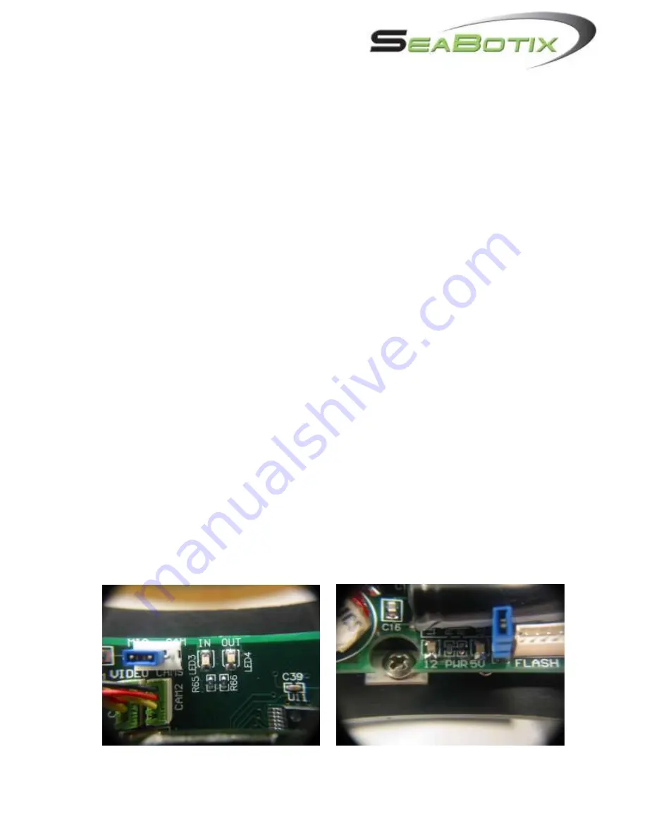
The following pictures show various components of the LBV system. Please refer to these
when troubleshooting. It will also be helpful to utilize a digital multimeter for some of the
checks required. Please remember that at no time should any component be plugged in or
unplugged while the SPS, ICC or LBV is energized during fault diagnosis.


