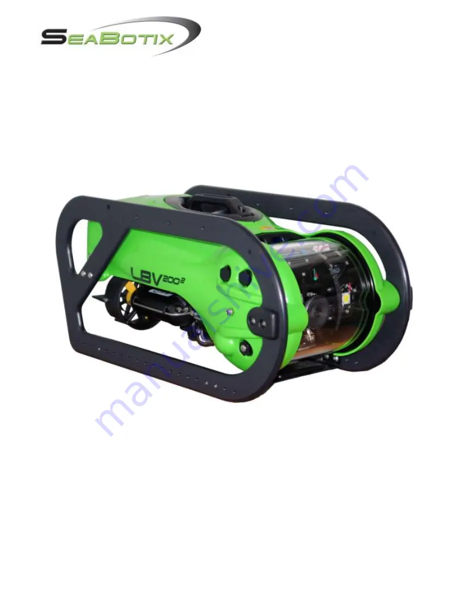
background image


Head Office

: SeaBotix Inc., 2877 Historic Decatur Road STE 100, San Diego, CA 92106 USA +1 (619) 450-4000 

Australia Office

: SeaBotix Inc. Australia Pty Ltd.8A Sparks Road, Henderson, WA 6166, Aus61 (0)8 9437-5400 


© 2009 by SeaBotix, Inc.  All Rights Reserved 


LBV200


Operators Manual 


DOCS-010 


Rev B 


The information, photographs, illustrations and descriptions contained in this manual are the 
property of SeaBotix Inc.  Unauthorized duplication and distribution is strictly forbidden.  
Additionally, SeaBotix Inc. reserves the right to alter any and all information contained in this 
manual. 

Summary of Contents for LBV2002

Page 1: ...alia 61 0 8 9437 5400 2009 by SeaBotix Inc All Rights Reserved LBV2002 Operators Manual DOCS 010 Rev B The information photographs illustrations and descriptions contained in this manual are the property of SeaBotix Inc Unauthorized duplication and distribution is strictly forbidden Additionally SeaBotix Inc reserves the right to alter any and all information contained in this manual ...

Page 2: ... 1 Thrusters 14 1 4 3 2 Camera s 14 1 4 3 3 Video Overlay 15 1 4 3 4 Accessories 15 1 5 Post Dive Inspection 15 1 6 Storage of System 15 1 7 Trimming ROV 16 1 8 Calibrating Compass 17 Section 2 LBV Controls 17 2 1 Operator Control Unit OCU 17 2 1 1 Joystick 18 2 1 2 Proportional Vertical Thruster Control Knob 18 2 1 3 Camera Control 18 2 1 3 1 Camera 18 2 1 3 2 Tilt 19 2 1 3 3 Focus 19 2 1 3 4 Int...

Page 3: ...isplay Type 25 2 3 3 4 User Text 25 2 3 3 5 Reset to Defaults 26 2 3 4 Calibrate Menu 26 2 3 4 1 Tilt Indicator 26 2 3 4 2 Temperature 26 2 3 4 3 Depth 27 2 3 4 4 Compass 27 2 3 4 5 Monitor 27 2 3 5 System 27 2 3 5 1 Thruster Motors 27 2 3 5 2 Software Version 27 2 3 5 3 Hours Run 28 2 3 5 4 Display Ext Temp 28 2 3 6 Options Menu 28 2 3 6 1 Camera Rotate 28 2 3 6 2 Audio Channel 28 2 3 6 3 Camera ...

Page 4: ...h use dirty water conditions 35 4 2 Every 50 hours 39 4 3 Every 500 hours 41 4 4 Long Term 41 4 5 Repairs 42 4 6 Software 42 4 7 Optional Components 42 Section 5 Troubleshooting 42 5 1 Introduction 42 5 2 Brief Theory of Operation 42 5 3 Troubleshooting Aids 43 5 4 Proper Operating Conditions 44 5 5 Fault Modes 45 Glossary of Abbreviations 48 Warranty 51 Limitations and Exclusions 51 Shipping Char...

Page 5: ...ation Throughout this manual information of special interest is highlighted with the following symbols Be sure to read and understand each of these important messages NOTE Information marked with this symbol is designed to help with the operation of the LBV by providing additional useful operating tips or facts CAUTION This symbol indicates a potential for harm and special care must be taken Poten...

Page 6: ...for the presence of water prior to connecting If the tether is cut chafed or otherwise damaged do not operate the LBV Do not open the LBV housing when the power is on Testing Each LBV system is carefully manufactured to ensure long term safe operation Prior to shipment every LBV is tested for proper operation including pressure testing to full operating depth Should a defect be found contact SeaBo...

Page 7: ...e power source o The LBV system employs a built in GFI circuit Do not connect to an outlet with its own GFI circuit o Do not use an uninterruptible power supply UPS Dry area Contents of packaging LBV200L LBV underwater vehicle Integrated Control Console Tether and reel Spares Tool Kit Manual CDROM Accessories if applicable CBA066 Reel to ICC video cable Note When unpacking the LBV after receipt in...

Page 8: ...st marked with a symbol This post should be electrically connected to the water in which your LBV will be deployed Also ensure that the AC outlets of the device are grounded to this point Always refer to your device s manual for proper grounding instructions Failure to properly ground the LBV system may potentially disable the LBV s ground fault interrupt circuitry and expose you and others to dan...

Page 9: ...1 3 1 LBV Step 1 Position the LBV so you that you can see the rear of the LBV Located at the upper right next to the flotation is an 8 contact male connector Step 2 Put a small amount of silicone grease on your finger This is GLA001 which is supplied with your order Step 3 Apply a small amount of the grease to the male pins on the bulkhead connector The grease is simply for lubrication and not a s...

Page 10: ...nnector onto the male bulkhead connector being careful to align the pins On the 3 contact connectors there is a single small pin used for alignment Step 8 Tighten the locking ring clockwise Do not over tighten Once the tether is connected to the LBV the next step is to connect the Integrated Control Console Surface Power Supply Again ensure that the Integrated Control Console Surface Power Supply ...

Page 11: ...hen operating Tritech sonar and or Linkquest tracking A Monitor B Circuit Breaker C Red LED POWER D Amber LED STATUS E Operator Control Unit OCU F OCU Power Switch 1 3 3 LBV150SE and LBV200L Fiber Optic Video Systems These LBVs come with tether reels that are designed for fiber optic video Video is output at the reel hub Therefore the hub and the ICC must be connected by a coaxial video cable CBA0...

Page 12: ...nspection and System Test Before placing the LBV in the water it is important to ensure that all LBVs operate as they are supposed to This process should be done each time the LBV is operated and will only take a moment to perform 1 4 1 Inspection 1 Visually look the LBV over for obvious damage Look at the condition of the view port seals thrusters etc for obvious damage 2 Check the tether for dam...

Page 13: ... from the vacuum valve Step 3 Connect the vacuum hose and ensure that the fitting is snug CAUTION Do not over tighten the seal screw as it could damage the sealing o ring Step 4 Pull vacuum to 10 inches of mercury and hold for 10 minutes watch for loss of vacuum The gauge should read the same after 10 minutes Step 5 Remove the vacuum tube Step 6 Insert and tighten the Phillips pan head seal screw ...

Page 14: ...ht to ensure that the lateral thruster operates correctly 3 Rotate the joystick clockwise then anti clockwise to Port and Starboard thrusters operate correctly 4 Rotate the vertical thruster knob on left side to ensure that the vertical thruster operates correctly 5 Press and hold the VERT key while selecting 1 0 on the keypad to adjust the gain control The value will change on the Video Overlay 6...

Page 15: ...ction After each use of the LBV take a moment to do a visual inspection of the LBV prior to storage It is good practice to submerge the LBV into a container of fresh water or rinse with a fresh water hose and wipe clean Check the LBV for damage Check the thrusters for debris caught near or in the propellers Quickly check the LBV functions to ensure that all systems operate correctly Check for lost...

Page 16: ...sh water will require slightly less lead depending on salt levels However every LBV has slightly different ballasting characteristics The operator may need to add move or subtract weights on the LBV for the desired operation in various bodies of water Step 1 Make sure that the tether is connected correctly as this will affect the buoyancy of the LBV Step 2 Place the LBV in the same type of water i...

Page 17: ...s rotated as slowly as possible Essentially you want to have the LBV pointed in all 360 degree increments This may take several minutes but ensures the most accurate reading The slower the LBV rotates and the greater the amount of rotations the more accurate the compass will be Once complete Press ENT Press PGRM NOTE This calibration is required initially and is then stored into memory However sho...

Page 18: ...ruster Control Knob Located on the left side of the OCU is the vertical thruster control knob Positioning your left thumb on the top of the knob will allow you to easily rotate the knob Rotating the knob forward causes the LBV to surface and conversely rotating the knob backward causes the LBV to dive This function can be reversed in the Options menu on LBVs with flash memory of ROV3 02 or higher ...

Page 19: ...e lamp being brighter and being dimmer The intensity of the light will be displayed on the Video Overlay L1 to L10 2 1 4 Accessories 2 1 4 1 Select If fitted with accessories such as grabber external lighting scaling laser or zoom camera push the SELECT button to cycle through the installed accessories 2 1 4 2 Arrow Keys Press the and keys to operate the accessories For the grabber the button clos...

Page 20: ...put from the OCU Once the desired depth is achieved press the DEPTH button and the LBV will maintain the depth The LED above this button will light when Auto Depth is on and a will appear next to the heading value on the Video Overlay Unlike Auto Heading both manual input and outside influences will be overridden in this mode To turn Auto Depth off simply press the DEPTH button 2 1 7 Power The POW...

Page 21: ...ust thruster gain control 1 10 2 20 3 30 0 100 The settings are displayed on the Video Overlay 2 1 11 Keypad The KEYPAD offers a variety of functions When adjusting the gain control for the thrusters the numbers are used to select the percentage of power available The keypad is used to input alphanumeric data on the user programmable annotation on the Video Overlay Also the keypad is used to manip...

Page 22: ...igits illustrate the 360 degrees of a compass heading To the right of heading is a or a followed by a numerical digit This is the turns counter 5 which represents the number of turns the LBV makes in one direction of 360º indicates turns in the clockwise direction indicates turns in the counter clockwise direction This is a valuable tool which allows the operator to keep track of the turns placed ...

Page 23: ...r to section 2 3 3 1 for setting of the date and the time 2 3 Menus The LBV has a variety of menus to allow the user to configure the LBV calibrate the LBV and run diagnostics To enter the main Menu press the PRGM key on the membrane keypad on the OCU 2 3 1 Quick Access Menu Note Accessories will appear when present The scaling laser is used here as an example 1 Acc Not Found a Pressing the 1 key ...

Page 24: ...he LBV to each user calibrating sensors viewing diagnostics and adjusting any installed accessories 1 Setup a Pressing the 1 key will take you to the Setup Main Menu 2 Calibrate a Pressing the 2 key will take you to the Calibrate Main Menu 3 Diagnostics a Pressing the 3 key will take you to the Diagnostics Main Menu 4 Options a Pressing the 4 key will take you to the Options Main Menu 2 3 3 Setup ...

Page 25: ... 1 Metric Seawater 2 Feet Seawater 3 Metric Freshwater 4 Feet Freshwater 2 3 3 3 Display Type a This menu is used to set the display type used with the LBV 1 NTSC PAL M N 2 PAL B G 3 PAL I 4 PAL D K 2 3 3 4 User Text a Pressing the 4 key will take you to the next screen for inputting user text To input user text simply press the appropriate key on the keypad to cycle through the letters until you ...

Page 26: ...sor indications Please contact SeaBotix Inc prior to or upon selecting this option 2 3 4 Calibrate Menu 2 3 4 1 Tilt Indicator a Pressing the 1 key will calibrate the camera angle indicator on the Video Overlay Once pressed the LBV will automatically rotate the camera to the 90º position and then back to the 0º position NOTE Do not calibrate the tilt function while the tilt function is reversed If...

Page 27: ...alibrate the compass heading information on the Video Overlay To calibrate the compass refer to section 1 8 Compass Calibration for more information 2 3 4 5 Monitor a This function does not apply to Fiber Optic Video equipped systems Pressing the 5 key will allow you to adjust the RF gain on the monitor on the LBV150BE and LBV150S systems 2 3 5 System 2 3 5 1 Thruster Motors Pressing the 1 key wil...

Page 28: ...Camera rotate allows the user to select how the camera rotation responds when the CAMERA button is pushed on the OCU Turn camera rotate on when you wish to view the same perspective on each camera as you switch between the two Turn camera rotate off when you wish to use the first camera to look straight ahead and the second to look down 2 3 6 2 Audio Channel a This function is not available on the...

Page 29: ... 3 4 5 Date Time Units Water Type Display Type User Text Reset To Default 1 2 3 4 5 Tilt Indicator Temperature Depth Compass Monitor 1 2 3 4 System Software Version Hours Run Display Internal Temp 1 2 3 Camera Rotate Audio Channel Camera Tilt See section 2 3 3 1 Keypad 1 4 See section 2 3 3 2 See section 2 3 3 3 See section 2 3 3 4 1 4 Keypad 1 3 See section 2 3 4 2 See section 2 3 4 3 1 5 See sec...

Page 30: ...nient handle located at the top of the LBV is the obvious way Simply lift the LBV into the water and begin deploying out the tether If the LBV is fitted with an optional protective bumper frame use any portion of the frame as a handle Do not drop the LBV into the water from heights greater than one meter Another option for deploying the LBV is to lower it by using the tether Connect the tether nor...

Page 31: ...on the male pins This will help with the installation as well as protection from the water and corrosion 3 4 Piloting The LBV has been designed for simple operation Once you have a basic understanding of the OCU and features of the LBV you will quickly discover how easy the operation of the LBV can be Listed below are some features of the LBV and how they aid operation Powerful thrusters Enables t...

Page 32: ...ment allows you to focus on the training rather than keeping the LBV out of trouble 3 5 1 Watching the LBV Initially operate the LBV in the swimming pool where you can see it respond to your commands Spending time practicing in this manner will help you to intuitively know how the LBV responds when you cannot see it For example You will have a better idea of how fast the LBV is moving related to t...

Page 33: ...th plenty of tether in the water Due to the power of the thrusters the LBV is fitted with a variable gain control There are two separate settings for gain control VERT and HORIZ These correspond respectively to surfacing diving and horizontal controls The amount of power available can be anywhere from 0 625 to the full 100 Reducing the amount of available power to the thrusters gives the user more...

Page 34: ...e DEPTH button NOTE In order for Auto Depth to work properly the LBV must be as close to NEUTRALLY buoyant as possible 3 9 2 Auto Heading Enabling Auto Heading will make the LBV hold a compass heading The LBV must be stable on the desired course when the Auto Heading key is pressed Rotating the joystick will override the Auto Heading and pressing the Auto Heading key a second time will turn the fu...

Page 35: ...ter each use dirty water conditions If the LBV is operated in excessively muddy or turbid water it is recommended that the bumper frame and shell be removed to clean thoroughly The procedure is very simple and will only take a few minutes Tools required 3mm Ball Driver TO090 4mm Ball Driver TO005 10mm Socket Driver TO012 2 Phillips Screwdriver TO015 Step 1 Remove frame mounted accessories External...

Page 36: ...teners removed 1 ea Lead Trim Weight if installed 2 ea M4 X 20 Button Head Screws 2 ea M4 X 25 Button Head Screws Step 7 Remove the two M5 x 12 button head screws securing the crossbar to the bumper frame Step 8 Lift off the bumper frame Step 9 Turn the LBV over to the opposite side Warning When placing the LBV on it s side care and attention must be paid to any cabling exiting the camera chassis ...

Page 37: ... the crossbar still attached Step 13 Remove the M6 Nyloc nut securing the front of the shell to the camera housing end cap TO012 Required Step 14 Remove the M4 x 50 Phillips head screw securing the rear portion of the shell to the float Note the grey standoff located between the shell and the float TO015 Required Step 15 Recover the grey standoff as you remove the M4 x 50 Screw Step 16 Remove the ...

Page 38: ...ra housing end cap TO012 Required Step 20 Remove the M4 x 10 Phillips head screw securing the rear portion of the shell to the float TO015 Required Step 21 Remove the 2 M4 x 20 Phillips head screws securing the shell to the float TO015 Required Step 22 Fasteners removed 2 ea M4 X 20 Pan Phillips 1 ea M4 X 10 Pan Phillips 1 ea M6 Nylock Nut Step 23 Remove the shell Step 24 Soak the LBV in a contain...

Page 39: ...mple and will only take approximately 25 minutes to complete Step 1 Follow procedure 4 1 1 for removing the bumper frame and shell Steps 1 to 17 Step 2 Place the LBV upside down Step 3 Remove the trim tab Step 4 Remove the two M4 x 10 Phillips head screws securing the thruster mounting tabs and the rear of the float to the backplane Step 5 Remove the two M4 x 10 Phillips head screws securing the m...

Page 40: ...lies and remove the Kort nozzles Step 10 Remove the three 3 Phillips head screws securing the lateral Kort nozzle to the lateral thruster and remove the Kort nozzle Step 11 Remove the black nylon Phillips head screw at the propeller end of each thruster end cap Four 4 total Step 12 Locate the GLA003 grease syringe in the basic spares kit BSK Push the syringe into the hole exposed from the removal ...

Page 41: ... for 500 hours it is recommended that the seals be replaced throughout the LBV including the thrusters Contact SeaBotix Inc at 619 450 4000 Ext 124 or email to service seabotix com or your nearest authorized service center information is available on the SeaBotix website www seabotix com 4 4 Long Term There is little need for long term maintenance as long as the LBV is taken care of and the 500 ho...

Page 42: ...ect Typically video monitoring and recording equipment is not included with the LBV system LBV s that include an Integrated Control Console are an exception to this rule and troubleshooting for these LBV s where they differ is covered later in this guide Furthermore some LBV s use fiber optics for the transmission of video and others use fiber optics for the transmission of both video and communic...

Page 43: ...emove supply voltage from all external equipment This feature prevents damage to the entire LBV system The high DC voltage from the surface allows for relatively low current on the tether greatly reducing its overall cross sectional diameter Designed into the power system is GFI circuitry that will de energize the 360 VDC at the Surface Power Supply Communication which takes place between the Oper...

Page 44: ...r Control Unit OCU Note the two LEDs above the Auto Head and Depth Buttons as well as the LED above the red power button Tether LBV End Note Pins 1 2 3 5 4 Proper Operating Conditions Please note Whenever the term normal is used in the Troubleshooting Guide it refers to the proper operating condition of that device or indicator After correctly connecting all the LBV components indications of the n...

Page 45: ... continuously lit with no flicker The user is able to operate all LBV functions i e Operate thrusters in all directions tilt the camera chassis select and focus cameras operate lamps open close grabber etc 5 5 Fault Modes Symptom No Video and No LBV Control This mode is usually accompanied by alternate flashing of the CC Auto Head and Depth LEDs OCU Power LED is lit Fault The SPS is not supplying ...

Page 46: ...o the backplane All LEDs are normal Cause One or more external LBV component has a short between 28 VDC and ground Fault Isolation Following the procedure manual remove one backplane component at a time reenergizing the LBV each time to test for normal operation of the remaining components Be advised that though all thrusters are modular and interchangeable the port and starboard thrusters operate...

Page 47: ...determine which thruster failed by utilizing the LBV s rotate function Rotating the LBV clockwise causes the port thruster to thrust forward while the starboard is thrusting aft By using this feature the troubleshooter can run each thruster in one direction at a time The faulty thruster needs to be replaced Note This failure can occur with grabbers and external lighting when these devices are bein...

Page 48: ...lable as a composite signal at the MUX hub of the tether reel system FSK Frequency Shift Keying A method of data transmission utilizing 2 5 channels of RS232 format for command and control of the LBV Data transmission to an external RS232 device with a remaining simplex channel for data to a device attached to the LBV GAK Grabber Attachment Kit Hardware All hardware descriptions prefixed with the ...

Page 49: ...ce Power Supply PCA Printed Circuit Card Assembly PIC Programmable IC Used extensively on the circuit boards to pre program them for functions as required POH Pull Out multiplexer Hub Part of the URS It contains the MUX as well as the termination point for the tether and the tether whip PSI Power Supply Interface circuit board part of the VPS QRS Quick Recovery System A secondary manual system use...

Page 50: ...ecovery of the LBV system UMB Tether Note Historically the term umbilical was used hence the UMB in the reference to the part numbers Going forward umbilical is now referred to as tether Example In deep water applications where the LBV is flown from another larger ROV or TMS Tether Management System an umbilical is the line that leads from the topside handling system to the larger ROV or TMS URS T...

Page 51: ...the LBV The limited warranty does not cover items subject to wear including but not limited to view ports outer shells o rings batteries protective bumper frame tether and propellers unless found to be defective in workmanship and or materials The limited warranty does not cover any alterations or modifications made to the LBV without prior authorization from SeaBotix Inc The limited warranty does...

Page 52: ...rned and the last four digits of the product serial number Items being returned must be in AS NEW condition AS NEW Condition means that there are no scratches marks blemishes on the item there are no signs of wear on the product or the cases and the product has not been altered or modified in any way The following conditions must be met you for warranty covered repairs Return the merchandise to us...

Reviews: