


Section 04
ENGINE
Sub-Section 05
(ROTARY VALVE)
04-05-6
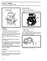
Measure shaft deflection near gear mounting ar-
ea.
TYPICAL
1. Rotary valve shaft
2. End bearing in place
Deflection must not exceed specified value. Re-
place shaft as necessary.
ASSEMBLY
Assembly is essentially the reverse of disassem-
bly procedures. However pay particular attention
to the following.
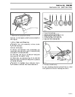
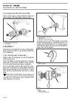
1, Bearing
To install end bearing in crankcase, use a pusher
(P / N 290 876 500).
1. Pusher
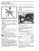
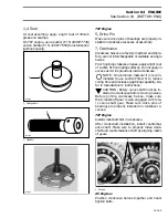
Position ball bearing shielded side towards rotary
valve.
TYPICAL
1. Shielded side here (towards gear)
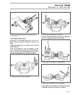
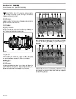
Push bearing until it stops on its seat.
TYPICAL
1. Bearing
2. Pusher
NOTE :
Do not remove plug against bearing
in crankcase half.
F01D2CA
2
1
A00B2JA
1
F01D2DA
1
F01D33A
1
2
'
Summary of Contents for Challenger 5896
Page 1: ......
Page 2: ......
Page 3: ...219 100 044 0 0 0 1996 Shop Manual 0 R ...
Page 152: ...Section 08 ELECTRICAL Sub Section 03 IGNITION SYSTEM 08 03 2 ELECTRICAL BOX Sportster F04H11S ...
Page 154: ...Section 08 ELECTRICAL Sub Section 03 IGNITION SYSTEM 08 03 4 ELECTRICAL BOX Speedster F04H26S ...
Page 251: ...Section 11 HULL DECK Sub Section 01 COMPONENTS 11 01 5 F04L3IS Loctite 242 ...
Page 274: ......


