


Section 04
ENGINE
Sub-Section 04
(BOTTOM END)
04-04-4
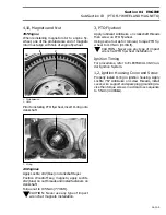
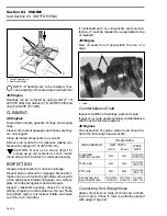
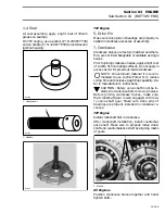
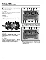
1. TDC gauge
2. Degree wheel
3. Hand tighten nut
4. Needle pointer
– Remove TDC gauge and install on
PTO side
.
– Bring
PTO
piston at Top Dead Center.
Interval between cylinders must be exactly 180°
therefore, needle pointer must indicate 180° on
degree wheel (360° - 180° = 180°).
Any other reading indicates a misaligned crank-
shaft.
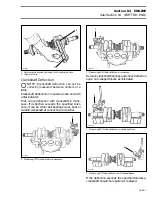
Crankshaft Alignment at Connecting
Rod Journal
Such misalignment may cause a crankshaft hard
to be manually turned. Verification can be done by
measuring deflection each end of crankshaft. Re-
fer to INSPECTION paragraph.
If deflection is found greater than specified toler-
ance, this indicates worn bearing(s), bent and / or
disaligned crankshaft.
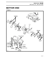
GENERAL
Engine has to be removed from boat to open bot-
tom end.
If crankshaft end seal(s) has / have to be replaced,
bottom end must be opened except for
MAG
side
seal on
787 engine
.
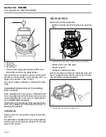
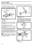
DISASSEMBLY
Remove the following partsþ:
– Ignition housing and PTO flywheel on opposite
side.
1. Separating ignition housing / armature plate from crankcase
– Rotary valve cover and valve.
– Engine support.
– Crankcase retaining screws.
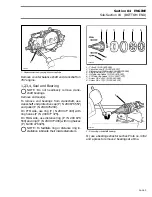
Insert screwdrivers between crankcase lugs and
pry to separate halves being careful not to dam-
age precision machined surfaces.
1. Separate halves by prying at provided lugs
1
F01D4IA
3
2
4
F01D4JA
1
F01D1KA
1
Summary of Contents for Challenger 5896
Page 1: ......
Page 2: ......
Page 3: ...219 100 044 0 0 0 1996 Shop Manual 0 R ...
Page 152: ...Section 08 ELECTRICAL Sub Section 03 IGNITION SYSTEM 08 03 2 ELECTRICAL BOX Sportster F04H11S ...
Page 154: ...Section 08 ELECTRICAL Sub Section 03 IGNITION SYSTEM 08 03 4 ELECTRICAL BOX Speedster F04H26S ...
Page 251: ...Section 11 HULL DECK Sub Section 01 COMPONENTS 11 01 5 F04L3IS Loctite 242 ...
Page 274: ......


