

Section 07 LUBRICATION SYSTEM
Sub-Section 02
(OIL INJECTION PUMP)
07-02-5
CHALLENGER
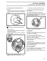
1. Must be full of oil
2. Bleed screw
Keep bleeding until all air has escaped from line.
Make sure no air bubbles remain in oil feed line.
Reinstall and tighten bleed screw.
Wipe any oil spillage.
Check small oil lines between pump and intake
manifold. They must be full of oil.
If not, run engine at idle speed while manually
holding pump lever in fully open position. Do not
activate throttle lever.
CAUTION : Water must be supplied to
cool engine with a garden hose.
CHECKING OPERATION
On Boat
Sportster and Speedster Only
NOTE :
Oil line supply must be full of oil.
See bleeding procedure above.
Unscrew banjo fittings from pump. Start engine
and stop it as soon as it fires.
Ensure that oil level in small oil lines is passed the
unpainted area. Repeat the procedure until this
condition is attained.
Reconnect banjo fittings with a washer on each
side and torque screws to 8 N•m (71 lbf•
in
). Start
engine and run at idle while holding the pump le-
ver in fully open position. Oil columns must ad-
vance into small oil lines.
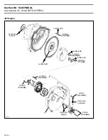
TYPICAL
1. Engine at idle
2. Fully open position
3. Oil columns advancing
If not, remove pump assembly and check the
pump gear for defects, replace as necessary. Test
pump as described belowþ:
NOTE :
Through normal use, oil level must
not drop in small tubes. If oil drops, verify
check valve operation in banjo fittings. Replace as
necessary.
On a Bench Test
All Models
The oil pump must be removed out of boat.
Connect a hose filled with injection oil to main line
fitting. Insert other hose end in an injection oil
container. Using a counterclockwise (reverse po-
sition) rotating drill rotate pump shaft. Oil must
drip from fittings in parts of rotary valve cover
while holding lever in a fully open position. If not
replace pump.
F04G0EA
2
1
1
-
'
F01G0EA
1
2
3
'
Summary of Contents for Challenger 5896
Page 1: ......
Page 2: ......
Page 3: ...219 100 044 0 0 0 1996 Shop Manual 0 R ...
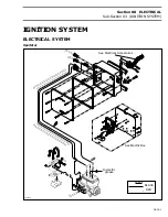
Page 152: ...Section 08 ELECTRICAL Sub Section 03 IGNITION SYSTEM 08 03 2 ELECTRICAL BOX Sportster F04H11S ...
Page 154: ...Section 08 ELECTRICAL Sub Section 03 IGNITION SYSTEM 08 03 4 ELECTRICAL BOX Speedster F04H26S ...
Page 251: ...Section 11 HULL DECK Sub Section 01 COMPONENTS 11 01 5 F04L3IS Loctite 242 ...
Page 274: ......