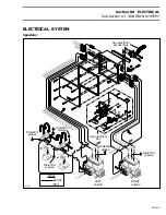
Section 08
ELECTRICAL
Sub-Section 01
(OVERVIEW)
08-01-4
787 ENGINE
The electrical system consist of different sub-sys-
tems where some are inter-related.
The magneto is coupled to the engine and produc-
es electrical energy for the charging system. Its
outputs are directed toward the charging system
and some circuits through the MPEM (Multi-Pur-
pose Electronic Module).
In the charging system, the battery supplies the
ignition system MPEM, the starting system, the
fuse block and the accessories. The following
gives an outline of each components.
There are different voltage types (A.C. (alternative
current) and D.C. (direct current)) and voltage lev-
els (0 to 40 000 Vac, 5 Vdc and 12 Vdc). There is
unregulated A.C. from magneto for the charging
system. For the charging system, the A.C. current
is rectified to D.C. and regulated to 12 Vdc for the
ignition system MPEM, gauges, fuse block, ac-
cessories and electrical system. The MPEM low-
ers the voltage level to 5 Vdc for its internal
circuitry and some external components (neutral
switch). For the ignition system, the D.C. voltage
from the battery is stepped up to 40 000 V. Keep
that in mind when dealing with voltages in the
electrical system.
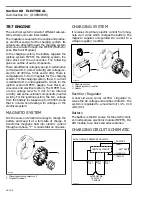
MAGNETO SYSTEM
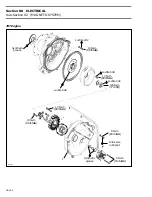
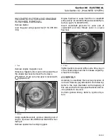
It is the source of electrical energy to charge the
battery and keep it at a full state of charge. It
transforms magnetic field into electric current
through a 3 phase, “Y” wound stator on 18 poles.
1. Charging system generator coil
2. Magneto flywheel
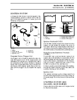
CHARGING SYSTEM
It receives its primary electric current from mag-
neto via 3 wires which charges the battery. The
magneto supplies unregulated AC current to a
voltage regulator / rectifier.
1. Magneto system
2. Voltage regulator / rectifier
3. Battery
Rectifier / Regulator
A dual 1/2 wave series rectifier / regulator re-
ceives the AC voltage and rectifies it into DC. The
system is regulated to a maximum of 14.5 - 14.8
volts (DC).
Battery
The battery is the DC source for the electric start-
er, multi-purpose electronic module (MPEM), DC-
CDI module, fuse block and all accessories.
CHARGING CIRCUIT SCHEMATIC
F04H23A
1
2
2
F04H24A
1
2
3
F01H4VA
DUAL 1/2 WAVE SERIES REGULATOR
POSITIVE
(RED)
BATTERY
CONTROL CIRCUIT
GROUND
(BLACK)
AC 3
(YE)
AC 2
(YE)
AC 1
(YE)
ALTERNATOR
180 WATT
3-PHASE
Summary of Contents for Challenger 5896
Page 1: ......
Page 2: ......
Page 3: ...219 100 044 0 0 0 1996 Shop Manual 0 R ...
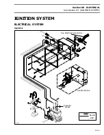
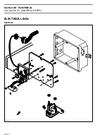
Page 152: ...Section 08 ELECTRICAL Sub Section 03 IGNITION SYSTEM 08 03 2 ELECTRICAL BOX Sportster F04H11S ...
Page 154: ...Section 08 ELECTRICAL Sub Section 03 IGNITION SYSTEM 08 03 4 ELECTRICAL BOX Speedster F04H26S ...
Page 251: ...Section 11 HULL DECK Sub Section 01 COMPONENTS 11 01 5 F04L3IS Loctite 242 ...
Page 274: ......


