


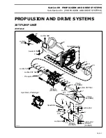
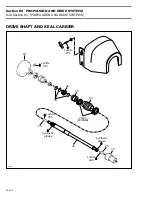


Section 09
PROPULSION AND DRIVE SYSTEMS
Sub-Section 01
(PROPULSION AND DRIVE SYSTEMS)
09-01-6
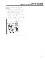
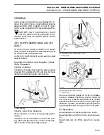
From inside bilge, disconnect coolant inlet hose
from impeller housing.
TYPICAL
1. Coolant inlet hose
Disconnect adjuster of steering cable from nozzle.
Remove ball joint fasteners to release reverse ca-
ble from reverse gate.
Detach ball joint of VTS from trim ring (
Challeng-
er
).
1,2,3,4,5, Screw, Sleeve, Bushing and
Nozzle
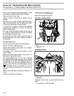
Remove 2 retaining screws and withdraw nozzle.
Push sleeves and bushings out of nozzle.
On challenger
, withdraw nozzle
/
trim ring as-
sembly by removing 2 retaining screws of trim
ring.
TYPICAL
1. Remove screws
7,8, Nut and Impeller Housing
Remove nuts retaining impeller housing to hull.
Withdraw pump unit and drive shaft together.
CAUTION : When removing pump unit, a
shim could have been installed between
hull and pump housing, be careful not to dam-
age shim. If shim is not reinstalled engine and
jet pump alignment will be altered.
If the drive shaft is jammed into PTO flywheel or
if bearing is seized on shaft at floating ring level, a
hammer puller can be used to withdraw drive
shaft.
DRIVE SHAFT PROTECTOR
If it is required to remove the protector tube, first
remove the boot on the thru-hull fitting (from in-
side of hull).
Squeeze retaining tabs of protector to withdraw
tube from thru-hull.
9,10,11, Venturi, Screw and O-ring
Remove 4 retaining screws and withdraw venturi
and reverse gate support (with gate).
TYPICAL
1. Remove screws
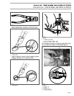
12,13,14,15, Ride Shoe, Screw and Grill
NOTE :
An impact screwdriver can be used
to loosen tight screws of grill.
Remove retaining screws of grill then withdraw it.
Remove retaining screws of ride shoe.
TYPICAL
1. Ride shoe screws
2. Grill screws
F04J0BA
1
F01J4IA
1
-
F01J4ZB
1
'
F01J0OB
1
1
2
Summary of Contents for Challenger 5896
Page 1: ......
Page 2: ......
Page 3: ...219 100 044 0 0 0 1996 Shop Manual 0 R ...
Page 152: ...Section 08 ELECTRICAL Sub Section 03 IGNITION SYSTEM 08 03 2 ELECTRICAL BOX Sportster F04H11S ...
Page 154: ...Section 08 ELECTRICAL Sub Section 03 IGNITION SYSTEM 08 03 4 ELECTRICAL BOX Speedster F04H26S ...
Page 251: ...Section 11 HULL DECK Sub Section 01 COMPONENTS 11 01 5 F04L3IS Loctite 242 ...
Page 274: ......


