Section 09
PROPULSION AND DRIVE SYSTEMS
Sub-Section 01
(PROPULSION AND DRIVE SYSTEMS)
09-01-19
TYPICAL
1. Apply Loctite 271 (red) on threads
CAUTION : Make sure thrust washer and
bearing have not slipped in shaft groove.
Using 2 screws previously removed from venturi,
secure impeller shaft holder tool to housing. In-
stall shaft holder tool in a vice.
NOTE :
Pump pressurization should be per-
formed at this time. If it leaks, it is easier to
determine where. Refer to pump pressurization
further in this section.
To ease impeller installation, apply liquid soap on
wear ring.
Insert impeller into wear ring. Manually rotate im-
peller and push so that it slides on impeller shaft
threads. Carefully engage threads making sure
they are well aligned.
Install impeller remover tool into impeller splines
and tighten.
CAUTION : Make sure thrust washer and
bearing are not wedged in shaft groove.
To check, manually pull and push impeller
housing, an axial play must be felt.
Torque impeller to 70 N•m (52 lbf•ft) then remove
tools.
CAUTION : Never use any impact wrench
to tighten impeller.
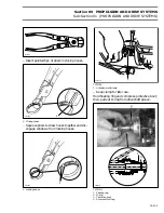
1. Impeller remover installer tool
2. Impeller shaft holder tool
17,28,29, Housing Cover, O-ring and
Loctite 518
Apply Loctite 518 on O-ring and install on housing
cover then carefully insert cover on impeller hous-
ing making sure to properly position plug on top
side.
1. Filler plug toward top side of pump housing
Apply Loctite 242 (blue) on screw threads and
evenly tighten cover screws. Torque to 7 N•m (62
lbf•in).
F01J1Q A
1
-
'
-
-
F01J2HA
1
2
F01J1RA
1
Summary of Contents for Challenger 5896
Page 1: ......
Page 2: ......
Page 3: ...219 100 044 0 0 0 1996 Shop Manual 0 R ...
Page 152: ...Section 08 ELECTRICAL Sub Section 03 IGNITION SYSTEM 08 03 2 ELECTRICAL BOX Sportster F04H11S ...
Page 154: ...Section 08 ELECTRICAL Sub Section 03 IGNITION SYSTEM 08 03 4 ELECTRICAL BOX Speedster F04H26S ...
Page 251: ...Section 11 HULL DECK Sub Section 01 COMPONENTS 11 01 5 F04L3IS Loctite 242 ...
Page 274: ......


