Section 09
PROPULSION AND DRIVE SYSTEMS
Sub-Section 01
(PROPULSION AND DRIVE SYSTEMS)
09-01-8
TYPICAL
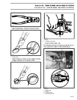
1. Pry boot cut
Withdraw drive shaft.
NOTE :
A jammed drive shaft can be re-
moved by holding pump unit by drive shaft,
slightly raised unit above a smooth surface, then
strike all around of impeller housing with a fiber
hammer. Corroded parts can be loosened by ap-
plying BOMBARDIER LUBE (P
/
N 293 600 006)
lubricant.
TYPICAL
1. Hold raised with drive shaft while striking
30, Fitting
Fitting can be removed with deep socket or vise
grip. Do not touch hose mounting area.
Fitting can be removed from pump housing with
following suggested tool
:
– Use a 14 mm (9/16 in) deep socket.
– Drill deep socket with a 14 mm (9/16 in) drill bit,
starting at hexagon head end as shown in fol-
lowing illustration.
– Drill a 2.40 mm (3/32 in) hole in center of deep
socket as shown in following illustration.
– Install 2.40 mm (3/32 in) roll pin in the center
hole.
1. Deep socket 14 mm (9/16 in)
2. Roll pin 2.40 mm (3/32 in)
A. 42.50 mm (1-43/64 in)
B. 36.80 mm (1-29/64 in)
17,18, Housing Cover and Screw
With pump assembly in horizontal position, re-
move 3 retaining screws.
Place container under cover to catch oil.
Using a fiber hammer, gently tap cover to release
it from impeller housing.
19, Impeller
Insert impeller shaft holder (P
/
N 295 000 082) on
impeller shaft flat end.
Using 2 screws previously removed from venturi,
secure shaft holder to housing. To ease removal
heat impeller center with a propane torch to ap-
proximately 150
°
C (300
°
F) to break the Loctite
bond.
Impeller is loosen using impeller remover tool (P
/
N 295 000 001).
Install shaft holder in a vice.
Insert special tool in impeller splines.
Rotate impeller remover tool counterclockwise
and unscrew completely impeller.
F01J0RA
1
'
F01J0SA
1
F01J2RA
A
B
2
1
Summary of Contents for Challenger 5896
Page 1: ......
Page 2: ......
Page 3: ...219 100 044 0 0 0 1996 Shop Manual 0 R ...
Page 152: ...Section 08 ELECTRICAL Sub Section 03 IGNITION SYSTEM 08 03 2 ELECTRICAL BOX Sportster F04H11S ...
Page 154: ...Section 08 ELECTRICAL Sub Section 03 IGNITION SYSTEM 08 03 4 ELECTRICAL BOX Speedster F04H26S ...
Page 251: ...Section 11 HULL DECK Sub Section 01 COMPONENTS 11 01 5 F04L3IS Loctite 242 ...
Page 274: ......


